
onsemi power semiconductors help control and convert electrical energy in power supplies, motor drives, chargers, and industrial equipment. MOSFETs and IGBTs act as controlled switches, while power diodes provide rectification and current paths that depend on the circuit topology.
For engineers, the challenge is choosing a device that meets efficiency, switching, and thermal requirements. For purchasing managers, it is securing the exact approved part with acceptable source documentation and delivery conditions. A genuine component can still be unsuitable for the circuit, so source verification and design approval need separate evidence.
This guide explains how MOSFETs, IGBTs, and diodes differ, what to compare before approving a replacement, and what evidence to request when sourcing onsemi parts.
What Are onsemi Power Semiconductors?
Power semiconductors handle electrical power rather than primarily processing information. Their performance affects conversion losses, cooling requirements, and the stresses experienced by other circuit components.
onsemi’s product range includes silicon MOSFETs, silicon carbide (SiC) MOSFETs, IGBTs, rectifiers, Schottky diodes, and power modules. A discrete device contains an individual switching or rectification function in its own package. A module can combine multiple power devices; the internal circuit must be checked before selection.
These categories describe different functions and technologies. “Power semiconductor” does not establish a common pinout, drive requirement, or qualification level. Neither does the manufacturer name establish whether a particular ordering code suits an automotive or industrial design.
Start a sourcing request with the full manufacturer part number and package. DuoLink’s onsemi component category provides a starting point for part-number inquiries, but each offer still needs availability and specification confirmation.
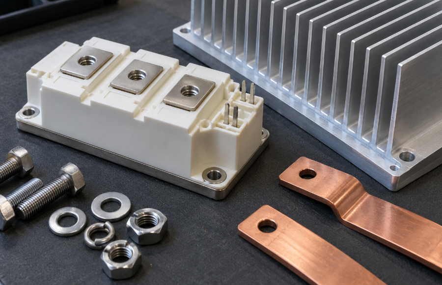
How Do onsemi Power MOSFETs Work, and Where Are They Used?
A power MOSFET uses gate-to-source voltage to control conduction between drain and source. Its insulated gate draws little steady-state current, but a driver must charge and discharge the gate during switching.
Silicon MOSFETs commonly serve DC-DC converters, power supplies, battery-related switching, and motor-control circuits. SiC MOSFETs extend the options for demanding high-voltage conversion, including charging and energy infrastructure applications. The choice depends on the complete circuit, not simply the material name.
Check On-Resistance at the Intended Gate Drive
Drain-to-source on-resistance, RDS(on), influences conduction loss. Compare it at the gate voltage and temperature relevant to the design. A headline resistance value measured under different conditions may give a misleading comparison.
Gate threshold voltage, VGS(th), indicates the onset of conduction at a specified small current. It is not the voltage that guarantees low resistance at the intended load. For a low-voltage control circuit, confirm that the datasheet specifies suitable performance at the available drive voltage.
Treat the MOSFET and Driver as a Pair
Lower resistance alone does not establish lower total loss. Gate charge, capacitance, switching conditions, and the commutating diode also matter. onsemi’s SiC gate-driver selection guidance explains why faster switching requires attention to drive current, parasitic effects, and unintended turn-on.
Before approving an alternate, ask engineering to review the recommended gate drive, driver capability, gate resistance, and layout. A SiC MOSFET should not be treated as a plug-in replacement for a silicon MOSFET merely because their voltage ratings match.
What Are onsemi IGBTs, and When Should You Use Them?
An insulated-gate bipolar transistor (IGBT) combines insulated-gate control with bipolar conduction. Its terminals are gate, collector, and emitter. Carrier injection can provide favorable conduction behavior in high-voltage, high-current applications, although stored charge introduces a switching trade-off.
IGBTs are candidates for industrial inverters, motor drives, welding equipment, and uninterruptible power supplies. Their suitability depends on the load profile, switching frequency, cooling, and circuit topology. Modern SiC devices also compete in applications historically served by IGBTs.
Compare collector-emitter saturation voltage, VCE(sat), together with turn-on and turn-off energy. Use equivalent current, temperature, gate resistance, and test conditions wherever possible. A device with an attractive conduction figure may have less favorable switching losses in the intended circuit.
onsemi’s IGBT Basic II application note discusses gate-drive selection and safe operating area (SOA), the permitted combinations of voltage, current, and operating conditions. Check any short-circuit capability in the specific datasheet; do not assume it applies to every IGBT.
For procurement, also confirm whether the device includes a co-packaged diode and whether its characteristics match the approved design.
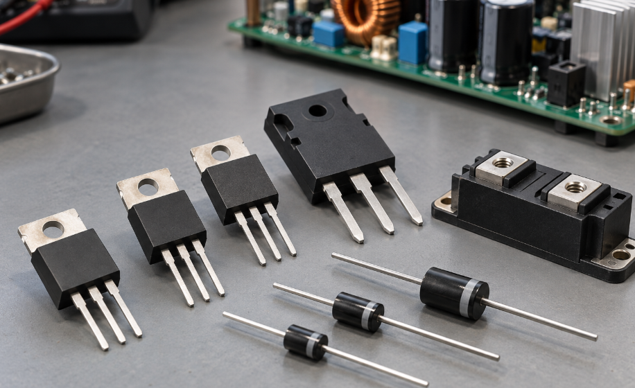
What Types of Power Diodes Does onsemi Offer?
A power diode generally conducts in its forward direction and blocks voltage in reverse within its ratings. It does not use a gate driver. Its recovery behavior and thermal limits can still affect the switching devices around it.
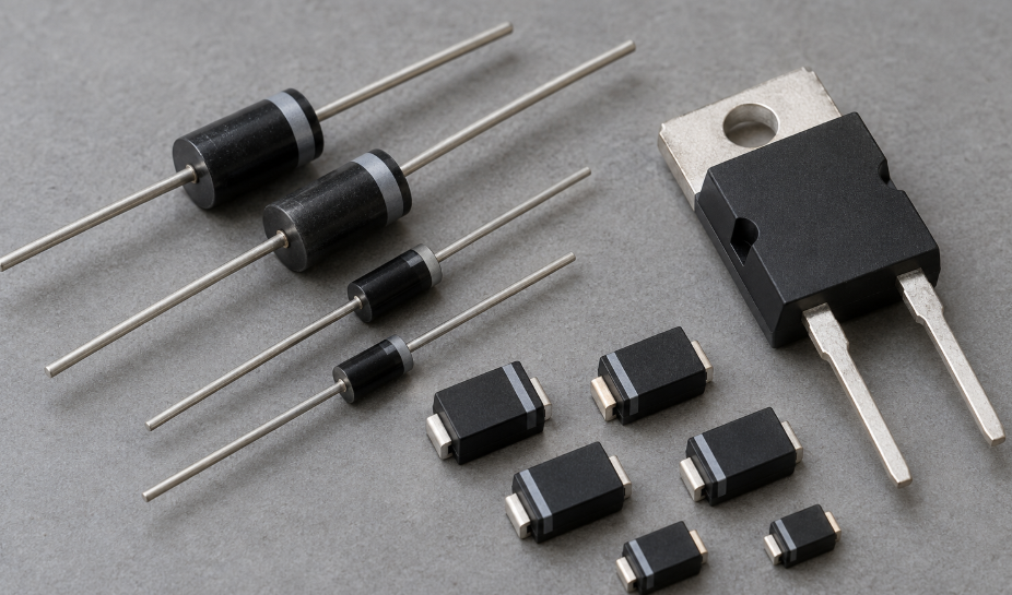
onsemi offers standard-recovery, fast and ultrafast rectifiers, Schottky rectifiers, and SiC Schottky diodes. Bridge and dual-diode arrangements describe circuit configurations; they do not, by themselves, define recovery speed.
| Diode family or configuration | Typical circuit role | Main selection checks |
|---|---|---|
| Standard-recovery silicon rectifier | Line-frequency rectification where recovery speed is less demanding | Reverse voltage, average current, surge conditions, cooling |
| Fast or ultrafast silicon rectifier | Switching rectification or freewheeling | Recovery time and charge, recovery behavior, forward voltage |
| Silicon Schottky rectifier | Rectification where low forward drop and fast response are useful | Forward voltage, reverse leakage at temperature, blocking voltage |
| SiC Schottky diode | High-voltage switching conversion | Capacitive charge, forward loss, surge capability, thermal limits |
| Bridge or dual-diode package | Several diodes combined for a circuit function | Internal connections, terminal assignment, ratings per diode or assembly |
SiC Schottky diodes avoid the minority-carrier recovery mechanism of conventional silicon PN diodes. Capacitive charging current remains, so “no reverse recovery” should not be interpreted as “no switching-related loss.”
Recovery specifications also require context. The onsemi MURA115/MURA120 datasheet, for example, specifies a maximum reverse-recovery time of 35 ns at a forward current of 1 A and a current-change rate of 50 A/µs. That figure does not describe every operating condition or every onsemi rectifier.
When replacing a dual rectifier, check whether it has a common anode or common cathode. An identical-looking package can contain a different circuit.
MOSFETs vs IGBTs: Which Fits Your Power Application?
There is no universal voltage or frequency boundary that selects the best technology. Silicon MOSFETs, SiC MOSFETs, and IGBTs overlap, and their relative performance changes with operating conditions.
| Comparison | Silicon power MOSFET | SiC MOSFET | Silicon IGBT |
|---|---|---|---|
| Conduction comparison | RDS(on) at relevant drive and temperature | RDS(on) at relevant drive and temperature | VCE(sat) at relevant current and temperature |
| Switching consideration | Charge, capacitance, diode recovery, topology | Fast transitions; driver and parasitic control are important | Turn-on/off energy and stored-charge tail |
| Typical evaluation context | DC-DC conversion, power supplies, battery circuits | High-voltage converters, chargers, energy systems | Motor drives and other high-power inverters |
| Replacement concern | Drive voltage, SOA, diode behavior, footprint | Drive limits, layout, protection, switching behavior | Drive, protection, co-pack diode, switching loss |
As an initial estimate, MOSFET conduction loss follows current squared times on-resistance. IGBT conduction loss follows current times its on-state voltage. For actual operation, calculate average loss over the waveform and account for temperature, duty cycle, and changing device characteristics.
A low-voltage battery circuit often favors a suitable silicon MOSFET. A high-voltage inverter may justify comparing IGBTs with SiC MOSFETs. Engineering should confirm which option meets the design requirements.
Ask engineering to compare total loss across the expected load range and confirm cooling, electromagnetic compatibility, and protection behavior. Purchasing can then assess the approved candidates for lifecycle and supply risk.
How Do You Select or Replace an onsemi Power Semiconductor?
Treat a replacement as an engineering change until compatibility has been established. Matching voltage, current, and package is only an initial filter.
Establish the Original Device and Operating Conditions
Record the full ordering code, approved datasheet, package drawing, and qualification requirements. Describe the maximum operating voltage and transients, current waveform, switching frequency, available gate drive, and cooling arrangement.
Keep absolute maximum ratings separate from intended operating conditions. A current rating obtained with a controlled case temperature does not establish the current a board can sustain in its actual enclosure.
Compare Electrical, Thermal, and Mechanical Details
Review switching characteristics alongside steady-state ratings. MOSFET comparisons need drive-dependent resistance and diode behavior; IGBT comparisons need conduction voltage, switching energy, and any co-packaged diode; rectifier comparisons need forward loss, recovery, leakage, and surge limits.
Check terminal assignments and the electrical connection of the metal tab. Compare dimensions, mounting arrangements, and the thermal path. A Kelvin-source connection, which separates the driver return from the main current path, can make a four-lead package behave differently from a three-lead version.
Validate Before Production Approval
Create a written comparison showing differences and unresolved conditions. Engineering should define suitable validation, which may include temperature measurements, switching-waveform checks, protection testing, and assessment across the intended load range.
Record approval in the BOM or approved-parts system before ordering production quantities. A cross-reference result identifies a candidate; it does not establish a drop-in replacement.
What Should Buyers Check Before Sourcing onsemi Power Semiconductors?
An approved design needs a corresponding procurement specification. Define the exact part, acceptable source route, required documents, and inspection criteria before issuing the purchase order.
Confirm Source Status and Lot-Specific Evidence
Verify any claimed manufacturer authorization through onsemi’s official channel information. An independent supplier and a manufacturer-authorized distributor represent different sourcing routes; an onsemi product listing does not establish authorization.
Ask whether an offer describes warehouse stock, upstream supplier stock, or material still to be sourced. Obtain current evidence for the offered lot where available, rather than relying on a generic catalog photograph.
| Purchasing check | Evidence to request | Action when unresolved |
|---|---|---|
| Exact part identity | Full ordering code, package, label and marking photographs | Resolve suffix or package differences before approval |
| Stock and batch | Quantity, location/status, date and lot codes, mixed-lot disclosure | Agree batch conditions and delivery basis in writing |
| Source documentation | Source type, available chain-of-custody records, relevant conformity documents | Assess whether evidence meets the application’s sourcing policy |
| Physical condition | Packaging, lead and surface condition, repacking history | Escalate unexplained inconsistencies for inspection |
| Qualification and handling | Part-specific qualification evidence and applicable handling instructions | Hold approval until required conditions are confirmed |
Set an Inspection Scope That Matches the Risk
Visual and dimensional inspection can identify inconsistencies, damage, or evidence of prior handling. They do not independently prove authenticity or full electrical performance. A basic meter check cannot establish high-voltage blocking capability or switching behavior.
Where risk justifies additional testing, specify the sample plan, parameters, conditions, acceptance limits, and responsible laboratory. Obtain approval for destructive testing before samples are consumed. Quarantine unexplained mismatches while the supplier and quality team investigate.
Apply ESD controls and the handling requirements for the exact package. Confirm moisture sensitivity where applicable instead of assuming all power devices need the same dry-pack treatment. Date code alone does not determine suitability; storage and physical condition also matter.
For automotive projects, obtain evidence for the precise qualified ordering code and the approval documents required by the customer. State destination-specific substance-documentation needs in the RFQ. Avoid accepting a broad family-level statement when the project requires part-specific evidence.
Conclusion
Selecting onsemi power semiconductors requires comparison of switching behavior, conduction loss, drive compatibility, and cooling. MOSFETs, IGBTs, and diodes each serve useful roles, but similar headline ratings do not make them interchangeable.
DuoLink Electronics is an independent electronic-component supplier offering component sourcing and BOM quotation support. To request sourcing support, send the complete onsemi part number, quantity, target delivery date, application, and packaging or documentation requirements. Include any approved alternatives and lot restrictions so the offer can be reviewed against your actual purchasing specification.
Frequently Asked Questions
Are All onsemi Power MOSFETs Silicon Devices?
No. onsemi offers silicon and silicon carbide MOSFETs. Check the technology and drive requirements for the exact part; the MOSFET label alone does not establish compatibility.
Can an IGBT Replace a MOSFET With the Same Voltage Rating?
Not without engineering review. Terminal functions, conduction behavior, switching losses, diode arrangements, and protection requirements can differ. Approve the change only after circuit-level validation.
Is Gate Threshold Voltage the Correct MOSFET Drive Voltage?
No. Threshold voltage describes the onset of conduction under a specified test condition. Select the drive voltage using the datasheet’s performance specifications and recommended operating guidance.
Are SiC Schottky Diodes Free of Switching Loss?
No. They avoid conventional minority-carrier reverse recovery, but capacitive charge and other circuit losses remain. Compare forward loss, charge, temperature, and surge conditions.


 English
  German
  Spanish
  French
  Chinese
  Italian