
Board-to-board connectors carry power and signals between printed circuit boards (PCBs). To choose the right pair, start with the board arrangement and required separation, then check pitch, contact count, electrical performance, mounting details, and the manufacturer’s approved mating combinations.
The tricky part is that two connectors can look almost identical and still be incompatible. A different height option, contact design, or part-number suffix can leave you with parts that fit the purchasing description but fail at assembly.
DuoLink Electronics supports connector sourcing and part-number inquiries for overseas buyers. This guide explains what to check before you request a quotation, approve a sample, or release a production order.
What Are Board-to-Board Connectors?
Board-to-board connectors create a separable electrical connection between PCBs without a cable between the mating interfaces. In a typical arrangement, one board carries a header or plug and the other carries its matching socket or receptacle. Some systems use a PCB’s plated edge as the mating interface.
They can connect a controller to a sensor board, a communication module to a main board, or a daughtercard to a backplane. The boards may sit parallel, meet at a right angle, or connect in another arrangement supported by the connector family.
For purchasing, treat the connection as a complete system. Both mating parts, their footprints, the board spacing, and the pin assignments need to work together. Approving one connector in isolation leaves important questions unanswered.
If you are comparing component options, DuoLink’s connector category provides a starting point for sourcing inquiries. Use the manufacturer’s drawings to decide whether a particular part suits your design.
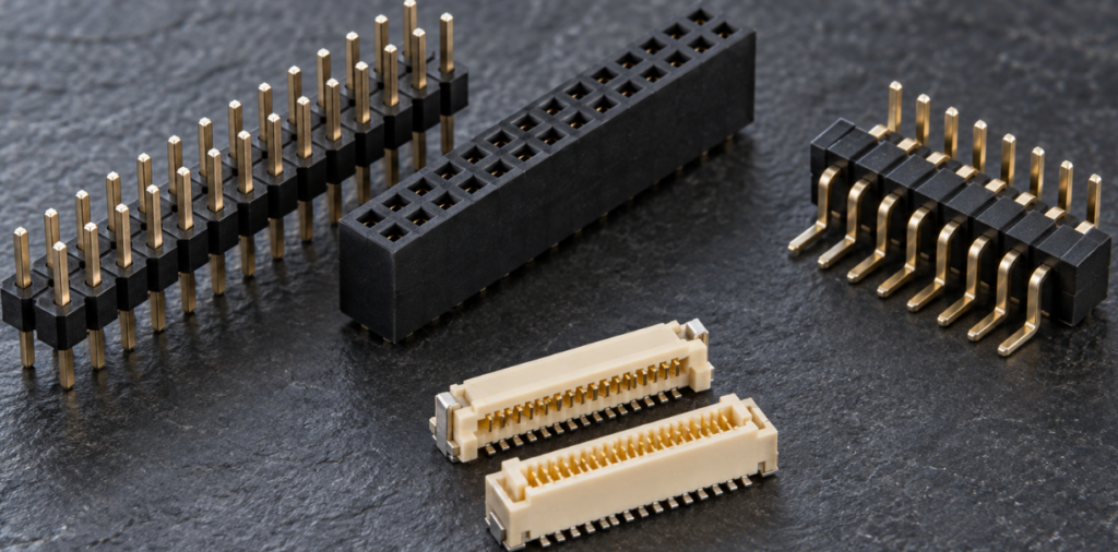
Common Types of Board-to-Board Connectors
Connector names describe different things. “Mezzanine” describes a board arrangement, while “floating” describes a mechanical feature. A single connector can belong to both groups.
| Type or feature | Where it may fit | Qué hay que comprobar |
|---|---|---|
| Header and socket systems | Modular boards and general board stacking | Exposed pin protection, polarization, contact length, and approved mating options |
| Fine-pitch mezzanine connectors | Compact assemblies with parallel PCBs | Mated height, routing space, alignment, and assembly tolerances |
| Right-angle board-to-board connectors | Daughtercards positioned perpendicular to a main board | Insertion direction, enclosure clearance, and mechanical support |
| Card-edge connectors | Removable boards with plated edge contacts | Board thickness, contact layout, edge preparation, and specified plating |
| Floating connectors | Assemblies where positional variation must be accommodated | Permitted movement in each axis and the manufacturer’s mating instructions |
| Dedicated power or hybrid connectors | Connections carrying power, sometimes alongside signals | Separate power and signal ratings, thermal limits, and approved pin assignments |
Header and socket systems
These systems offer options for board spacing, contact count, and orientation. An unshrouded header leaves its pins exposed, so handling and assembly alignment need attention. A shrouded or polarized design can help guide mating, but its exact features must match the application.
Check the contact engagement as well as the visible housing size. A longer pin is useful only when the matching socket and approved assembly dimensions support it.
Mezzanine and floating connectors
Mezzanine connectors join parallel boards. Fine-pitch versions can save board area, although routing, soldering, and inspection become part of the selection decision.
Floating connectors allow specified movement to accommodate positional variation. Hirose’s FX23 family is one documented example. The permitted movement belongs to the particular connector design; it does not remove the need to control board position or insertion direction.
When an assembly uses several connectors between the same boards, ask engineering to review their combined tolerances. Each connector may fit on its own while the complete assembly is difficult to mate.
How to Choose Pitch, Pin Count, and Stack Height
Start with a sketch of the installed boards. Show the mating direction, board spacing, tallest components, mounting holes, and nearby enclosure walls. This makes catalog filtering much more useful.
Choose pitch around the complete PCB layout
Pitch is the center-to-center distance between adjacent contacts in the specified row or array. A smaller pitch generally allows greater contact density, but it also affects pad dimensions and routing space.
Before choosing the smallest available option, ask the PCB designer and assembler to review the recommended footprint. Check whether traces can escape from the pads, whether vias fit where needed, and whether the assembly process can meet the connector’s placement and soldering requirements.
A connector that saves housing space may still increase the difficulty of the surrounding PCB layout.
Count power and ground contacts before fixing the pin count
Build the pin assignment before selecting the contact count. Include signal contacts, differential pairs, power paths, ground returns, and any reserved positions.
For example, a design with 20 signal connections does not automatically need a 20-position connector. Ground allocation and power requirements may increase the count. This is an illustrative planning example; the correct allocation depends on the circuit.
Check how the manufacturer describes positions. A catalog entry may state positions per row, total circuits, or a combination of signal and power contacts.
Confirm stack height from the mating drawing
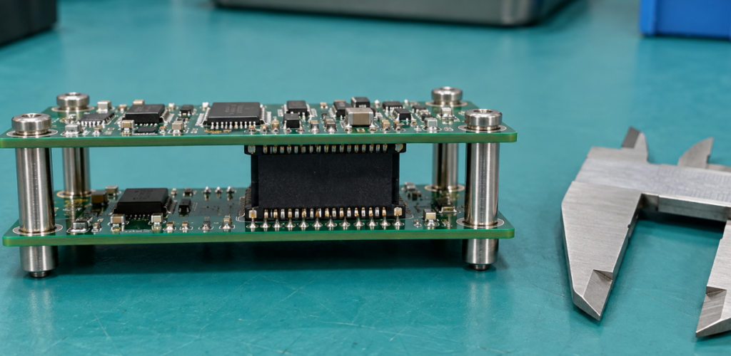
For parallel boards, stack height usually refers to a defined separation between board reference planes when the connectors are mated. Follow the manufacturer’s definition and tolerance.
Do not calculate it by adding the heights of the two unmated housings. Their mating interfaces overlap, and different plug or socket options may produce different approved heights.
Suppose your enclosure needs a nominal 10 mm board separation. The next step is to find a documented mating pair with that separation, then check component clearance and the assembly tolerance. Choosing two parts that each appear to be 5 mm tall does not establish a valid 10 mm connection.
Record both complete part numbers and the drawing revision used for approval.
How to Check Current Ratings and Signal Performance
Electrical suitability needs its own review, even after the dimensions match.
Read the conditions behind the current rating
A headline current rating is not enough to approve a power path. Check the ambient temperature, permitted temperature rise, number and arrangement of energized contacts, and the PCB or fixture used for testing.
Samtec’s discussion of current-carrying capacity and temperature rise explains why thermal conditions matter. Use the documentation for the exact candidate connector when making a design decision.
Ask for the applicable derating data if several contacts will carry current simultaneously. Do not multiply a single-contact rating by the contact count and treat the result as an approved total current.
Review voltage rating, insulation requirements, and operating temperature separately. For a hybrid connector, power contacts and signal contacts may have different limits.
Match signal evidence to the proposed configuration
A connector advertised for high-speed use still needs to fit your channel. The interface, data rate, signal edge rate, differential or single-ended signaling, and ground allocation all affect the review.
The manufacturer’s performance evidence should identify the tested mating pair, stack height, pin assignment, and PCB launch conditions. Where available, request suitable S-parameter files, which describe the interconnect’s frequency-dependent behavior, for engineering analysis.
Samtec’s signal-integrity FAQs explain why system topology, impedance, edge rate, and crosstalk requirements belong in connector selection. A published data-rate figure does not approve the complete PCB channel.
For a fast interface, engineering should review the connector together with its PCB routing and return paths. Procurement can collect the evidence, but a stock listing or matching pitch cannot establish signal performance.
What to Consider for PCB Mounting and Mechanical Reliability
The mounting method has to suit both the PCB process and the way the boards will be assembled and serviced.
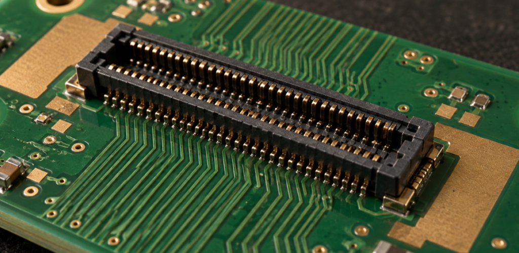
Surface-mount connectors need the correct land pattern, coplanarity control, soldering process, and inspection approach. Through-hole versions need suitable hole dimensions and a compatible soldering process. Press-fit products require the manufacturer’s specified hole construction and insertion procedure.
Avoid using a footprint from a visually similar part. Mounting tabs, locating pegs, pad dimensions, and keep-out areas can differ within the same broad family.
Plan support around mating forces
Review insertion and withdrawal forces for the selected contact count. Decide how the assembler will support the boards during mating and how a service technician will separate them.
Standoffs, guide features, or other support may be needed to control alignment and prevent excessive board flex. Their dimensions must agree with the connector’s permitted engagement. A connector should not have to absorb an unplanned enclosure load.
A useful sample check is to assemble the actual boards with their intended fasteners and enclosure constraints. A loose connector pair on a desk cannot reveal every installation problem.
Match durability evidence to the application
Check the specified mating-cycle rating and the conditions under which it was evaluated. A removable service module has different needs from an assembly connected once during production.
For equipment exposed to vibration, shock, humidity, or temperature variation, request the relevant manufacturer’s qualification information. Review contact finish and plating options against that evidence.
Qualification of a connector family does not automatically qualify the finished product. Automotive, medical, and other controlled applications may require additional customer or engineering approval.
How to Verify Mating Compatibility and Part Numbers
Matching pitch and pin count only narrows the search. It does not establish that two connectors will mate correctly.
The manufacturer’s mating information should identify a compatible counterpart. Check the complete part numbers, including suffixes for height, contact finish, termination, orientation, polarization, and packaging where applicable.
| Check | Evidence to use | What should stop approval |
|---|---|---|
| Approved mating pair | Manufacturer mating table or written confirmation | No documented match for the proposed parts |
| Mechanical fit | Drawings, board references, tolerances, and CAD review | Height, alignment, or clearance mismatch |
| Electrical suitability | Product specification and relevant performance data | Required current, voltage, or signal performance is unsupported |
| PCB mounting | Recommended footprint and processing instructions | Pad, hole, peg, or hold-down mismatch |
| Pin mapping | Schematics and the drawing’s stated viewing direction | Mirrored numbering or inconsistent signal assignments |
| Proposed substitute | Documented comparison and engineering approval | Compatibility claimed only from appearance or basic dimensions |
Check pin numbering from the stated viewpoint
Connector drawings may show the mating face, mounting face, or another view. The two boards can appear to have matching layouts while their signals are reversed.
Compare the schematic and footprint with each drawing’s viewing direction. Verify pin 1 and the complete mapping across the connection before approving PCB fabrication.
Keep substitute approval separate from stock approval
An available substitute may require replacing both mating halves or changing the PCB footprint. Even if it physically mates, differences in contact finish, engagement, durability, or electrical behavior may still matter.
Request a comparison against the original parts and obtain engineering approval before substitution. If a seller cannot document compatibility, keep the alternate off the approved BOM until the questions are resolved.
What to Confirm Before Ordering Board-to-Board Connectors
An RFQ is easier to answer when it includes the full manufacturer part numbers for both halves, quantities for each, target delivery date, and the approved mating height. Attach the relevant drawing or specification if your requirements go beyond the standard part description.
DuoLink’s BOM sourcing support can help organize component inquiries. Keep the two connector halves on separate BOM lines and note their relationship so one cannot be substituted without reviewing the other.
Separate availability from technical approval
Confirm whether the quoted quantity is physically held by the seller, held elsewhere in the supply chain, or subject to procurement. Ask for the expected shipment date, packaging format, and applicable minimum order or packing quantity.
Reels, trays, tubes, and cut packaging may suit different assembly processes. Check reel orientation and pick-and-place provisions where relevant.
For an independent sourcing route, establish which supply records, manufacturer labels, and conformity documents can actually be provided. Photographs and labels help screen a shipment; they do not prove authenticity on their own.
Set incoming checks before shipment
Agree on the acceptance and discrepancy process before ordering. For a new source, an incoming plan may include part-number and label review, visual inspection, dimensional checks, and a controlled mating check using approved counterparts.
Inspect housings for cracks, contacts for damage or contamination, and solder tails or hold-downs for deformation. Visual checks cannot establish hidden plating thickness or long-term durability. Any additional testing needs defined methods and acceptance criteria.
Request part-specific material declarations when your customer or destination requires them. A generic supplier statement is not a substitute for documentation covering the ordered parts.
A practical release sequence is:
- Engineering approves the mating pair, footprints, pin mapping, and electrical requirements.
- Purchasing confirms quantity, sourcing route, packaging, documentation, and delivery terms.
- Samples undergo the agreed assembly and application checks when required.
- The purchase order records approved parts, substitution restrictions, and acceptance requirements.
For repeat production, check lifecycle status and relevant change notices. Review any alternate with engineering before a shortage makes the decision urgent.
Conclusión
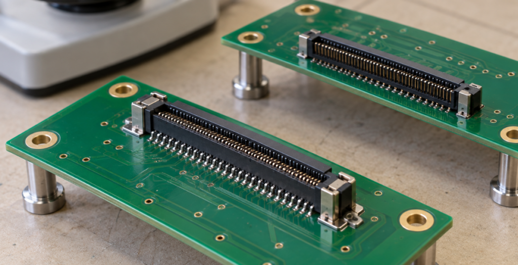
Choose board-to-board connectors as a complete mating system. Confirm the board arrangement and spacing, then review contact allocation, electrical evidence, mounting details, and mechanical support. Before ordering, resolve every part-number suffix and document which counterpart is approved.
DuoLink Electronics is an independent electronic-component supplier supporting connector inquiries and BOM sourcing. To request a quotation, send both manufacturer part numbers, quantities, target delivery date, and documentation requirements. If you need an alternative, include the original drawings and application requirements so the proposed option can go through engineering review.
Preguntas frecuentes
Are board-to-board connectors with the same pitch interchangeable?
No. Housing geometry, contact design, mated height, polarization, and electrical performance may differ. Use manufacturer mating information and engineering review to approve compatibility.
How do I choose the correct stack height?
Start with the required board separation and clearance. Select an approved mating pair using the manufacturer’s reference planes and dimensional tolerances, then check it against the complete assembly.
Can I calculate total connector current by multiplying the rating by the number of pins?
That does not establish a safe design limit. Check the applicable thermal data, energized-contact arrangement, PCB conditions, and ambient temperature. Engineering should approve the power path.
Do I need a floating connector when two boards use several connectors?
It may help accommodate positional variation, but the answer depends on the complete tolerance analysis. Check the permitted movement, guidance features, and mating procedure for the selected system.
What should I check before approving a replacement connector?
Review both mating halves, PCB footprints, pin numbering, stack height, finish, electrical performance, and durability. Obtain engineering approval and perform the agreed validation before changing the BOM.


 Spanish
 English
 German
 French
 Chinese
 Italian