Two connectors can look almost identical in a product photo and still refuse to fit together. The pin count matches. The spacing looks right. But the latch, contacts, or PCB footprint is different, and the parts you ordered can’t be used.
That’s why choosing electronic connector types takes more than finding a familiar shape. Board-to-board, wire-to-board, FFC/FPC, circular, RF, and other connector families each solve a different connection problem. The right one needs to suit your electrical requirements, fit the assembly, and work under the conditions your product will face.
DuoLink Electronics supports component sourcing, including connectors. This guide walks through the common types and the details worth checking before you place an order, whether you’re buying for a new design or replacing an existing part.
What Are Electronic Connectors?
Electronic connectors join circuits between wires, cables, printed circuit boards (PCBs), or equipment interfaces. They carry power, signals, or data. Many let you disconnect the assembly when you need to replace a component or service the equipment.
What you buy as a “connector” can vary. A PCB-mounted receptacle may arrive as one complete component. A cable connector might need a plastic housing, separate metal contacts, seals, and strain relief. If the quotation only covers the housing, you’ll still need the other parts before you can assemble it.
The names can be confusing too. “Wire-to-board” tells you what the connector joins. “Circular” describes its shape. “Power” tells you what it carries. One product can fit all three descriptions. Use those terms to narrow your search, then use the manufacturer’s full part number to specify the purchase.
Common Electronic Connector Types and Their Uses
Board-to-Board Connectors
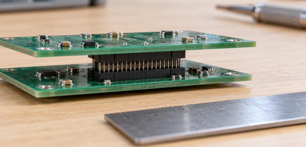
These connectors join two PCBs directly. The boards might sit in a parallel stack, meet at a right angle, or lie in the same plane. You’ll find these arrangements in control modules, communications equipment, and compact electronic assemblies.
Board spacing deserves attention. A connector may fit the space on your PCB but leave the assembled boards too close together or too far apart. Check both halves of the mating pair, the resulting stack height, nearby component clearance, and the allowed alignment tolerances before approving it.
Wire-to-Board Connectors
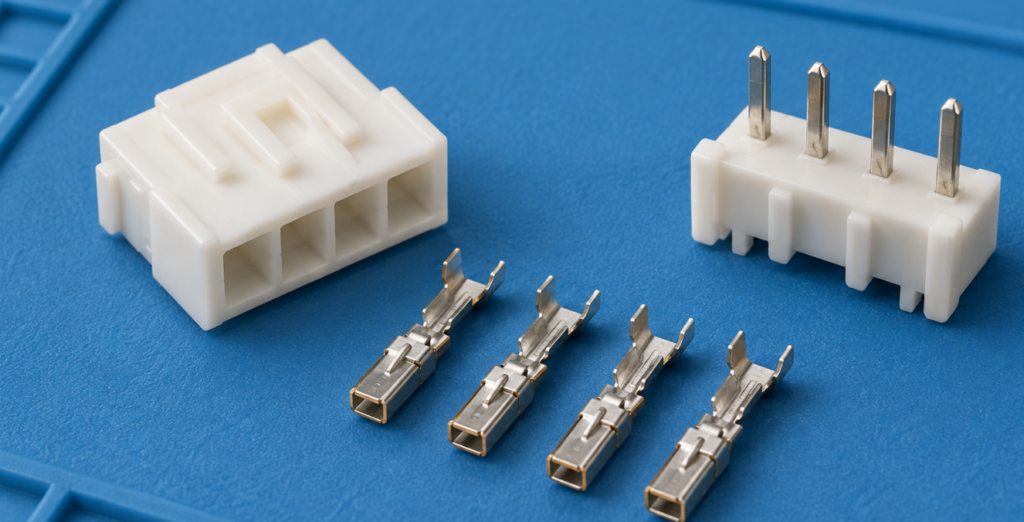
If you’re connecting a fan, sensor, display, or internal power cable to a PCB, a wire-to-board system may be what you need.
Many systems have three separately ordered parts: the PCB header, the cable housing, and the crimp terminals inside that housing. TE’s wire-to-board portfolio includes systems built this way. A description such as “four-pin connector” leaves too much open; list the required components by part number.
The wire matters as well. Check the terminal’s accepted conductor size and insulation diameter. A contact can fit the housing cavity without being suitable for the wire you plan to use.
Wire-to-Wire Connectors
Wire-to-wire connectors let you join two cable sections without a PCB between them. They’re useful when a harness needs a removable connection for installation or servicing.
Make sure you’ve identified both mating halves, the contact types, circuit count, and locking arrangement. For a sealed assembly, follow the manufacturer’s instructions for unused cavities too. You may need cavity plugs as part of the order.
Pin Headers and Sockets
Pin headers and sockets appear in programming interfaces, development boards, and low-speed board connections. They come in different row arrangements, orientations, and housing styles, including exposed and shrouded versions.
Pitch means the center-to-center distance between adjacent contacts. Matching it is a starting point. You also need to compare pin dimensions, row spacing, engagement length, and polarization. With an exposed header, ask how the assembly will prevent someone from plugging it in backward or one position off.
FFC and FPC Connectors
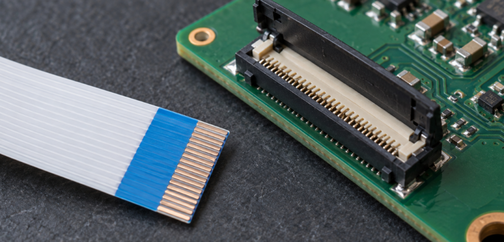
Flexible flat cable (FFC) and flexible printed circuit (FPC) connectors help connect thin flexible interconnects to a PCB. They’re often used in displays and compact electronic products.
Here, a small detail can stop the connection from working. The cable needs the right circuit count, pitch, thickness, and exposed-contact orientation for the connector. Molex’s FFC/FPC documentation includes thickness and dimensional requirements for this reason. The actuator arrangement matters too.
Before buying a replacement, look at both ends of the cable and both connector drawings. A cable can have the right width while its contacts face away from the connector’s contact side.
Terminal Blocks
Terminal blocks connect wires through screws, spring clamps, or push-in mechanisms. They’re common in control equipment and products that need field wiring.
Check which conductor types and sizes the terminal accepts, how much insulation to strip, and how the part mounts. Follow its installation instructions. If you’re buying a pluggable version, specify the wire-side plug and board-side header together. Equal pitch doesn’t establish that two versions will mate.
Circular and Sealed Connectors
Circular connectors are used in industrial sensors, automation equipment, and cable assemblies. Depending on the family, the connection may lock with a thread, bayonet, or another mechanism.
Look beyond the shell size. Compare the coding, contact layout, pin assignment, cable entry, and mounting dimensions.
For sealing, read the conditions attached to the rating. TE, for example, specifies protection conditions for its heavy-duty sealed family with the connector mated and installed as required. You can’t assume the same protection applies when the connector is open or assembled differently.
RF and Coaxial Connectors
RF connectors join coaxial cables and radio-frequency circuits. SMA and BNC are familiar examples, but each family includes variants for different cables and mounting arrangements.
Start with the required impedance and frequency range, then match the exact interface and cable type. With threaded connectors, inspect the center contact as well as the outer body. Similar-looking versions can use different contact arrangements. If the identity is uncertain, request the mating-interface drawing rather than relying on the photo.
USB, Modular Jacks, and Other External Interfaces
USB receptacles, Ethernet-related modular jacks, D-sub connectors, and audio/video connectors connect equipment to the outside world. The interface requirements and mounting details both need to match your design.
USB Type-C is a useful example of why appearance isn’t enough. It describes a connector interface, but doesn’t by itself tell you the supported data speed or USB Power Delivery capability. The USB-IF language guidelines distinguish Type-C from USB 3.2 and USB4. State the required implementation in your specification.
For an Ethernet jack, check whether the design needs integrated magnetics, shielding, LEDs, and a particular PCB footprint. Use the equipment schematic and approved drawing to settle those details.
Power Connectors
Power connectors supply batteries, boards, modules, and equipment. They can use several physical arrangements, including wire-to-board, wire-to-wire, and circular formats.
A catalog current rating needs context. Molex product specifications can include derating data based on temperature rise and the number of loaded circuits. Check the conditions behind the rating before applying it to your design. Wire size, circuit count, and ambient temperature can change the assessment.
Electronic Connector Types Comparison Table
Some of these categories overlap. Use this table to find a starting point, then check the specific part and its mating counterpart.
| Connector type | Typical use | What to check | Ordering mistake to watch for |
|---|---|---|---|
| Board-to-board | Direct PCB connection | Mating pair, stack height, footprint, alignment | Getting the board spacing wrong |
| Wire-to-board | Cable or harness to PCB | Header, housing, contacts, wire size | Buying the housing without terminals |
| Wire-to-wire | Removable harness joint | Both halves, locking, contacts, seals | Ordering the wrong mating half |
| Pin header/socket | Programming or low-speed connection | Pitch, rows, pin dimensions, engagement | Assuming equal pitch means a match |
| FFC/FPC | Display or compact flex connection | Contact side, cable thickness, pitch, actuator | Choosing the wrong contact orientation |
| Terminal block | Field wiring and control equipment | Wire range, strip length, mating plug/header | Buying an incompatible counterpart |
| Circular/sealed | Industrial sensors and exposed wiring | Coding, pinout, installation, sealing conditions | Matching the shell but missing the coding |
| RF/coaxial | Antenna or RF connection | Impedance, frequency, interface, cable | Choosing a part that fits but doesn’t meet electrical needs |
| External interface | Data or peripheral connection | Implementation, footprint, shielding | Assuming shape guarantees capability |
| Potencia | Power distribution | Derating, contacts, wire size, temperature | Using the catalog maximum without reviewing conditions |
How to Choose the Right Electronic Connector
Start With the Connection and Operating Requirements
Begin with two questions: what are you connecting, and how will the assembly be used? Record the available space, cable routing, assembly access, and whether someone will need to disconnect it for service.
Then define the electrical requirements. A low-speed sensor connection and a high-speed data link need different checks, even if their housings look similar. Write down the operating voltage, expected current, signal requirements, and environmental conditions before comparing candidates.
Samtec’s connector selection guide gives a useful overview of factors such as pitch, orientation, plating, retention, and manufacturing method.
Review the Complete Assembly
Review the connector together with its mate, cable, and termination process. Your engineering team should compare the operating temperature, mating-cycle requirement, contact plating, and retention method with the application’s needs.
Think about how often the connection will be used. An internal connector assembled once has a different service pattern from an external port that’s unplugged regularly. Ask for the durability specification rather than assuming the family name settles the question.
For a high-current connection, get the relevant derating information. For high-speed or RF connections, collect the performance data and agree on system validation. Purchasing can gather the documents, but engineering needs to approve the part’s suitability.
Include Production and Supply Requirements
The part also needs to work with your assembly process. Will it arrive in packaging your placement equipment can handle? Can it withstand the intended soldering process? Do you have the approved crimp tooling?
Include the full part number and acceptable packaging in your BOM sourcing request. Before adopting a new connector family, confirm how you’ll source both mating halves, terminals, and accessories. Finding one header in stock doesn’t mean the rest of the assembly is available.
How to Check Connector Compatibility
Compare Drawings, Part Numbers, and Pin Assignments
If the manufacturer lists mating part numbers, start there. Compare the interface drawing, keying, latch, contact arrangement, and mounting dimensions. Check the pin assignment separately. Two halves can fit together while connecting the wrong circuits.
A PCB replacement needs another check: the footprint. Compare the pad or hole positions, mounting pegs, retention tabs, board thickness requirements, and body clearance. A connector might accept your existing cable but fail to fit the board.
For a cable assembly, confirm the terminal and housing combination in the manufacturer’s application instructions. TE’s Universal MATE-N-LOK application specification shows the kind of detailed assembly guidance worth requesting for your chosen family.
Use Samples to Resolve Uncertainty
Here’s a hypothetical example. You’re replacing a six-position wire-to-board connector. Two candidates have the same nominal pitch, but one has a different latch and terminal geometry. In a photo, it looks close enough. In the drawings, it becomes clear that your existing harness won’t work with it.
Before approving an uncertain replacement, review a sample against the actual counterpart. Check fit, orientation, retention, and assembly access using the manufacturer’s instructions. Ask engineering to define any electrical or environmental tests needed before release.
A successful mating check tells you something useful about fit. It doesn’t prove long-term durability, current capability, or authenticity. Keep a cross-brand alternative under review until the required properties have been checked and approved.
What to Confirm Before Ordering Connectors
A useful RFQ tells the supplier exactly what you need and gives them a way to flag differences. If you’re buying a new connector assembly, include the related parts rather than sending only the housing number.
| Item to confirm | What to send or request |
|---|---|
| Exact identity | Manufacturer, full part number, suffix, approved drawing revision |
| What’s included | Header, housing, contacts, seals, locks, backshell, or complete assembly |
| Mating arrangement | Counterpart references and approved pin assignment |
| Assembly requirements | Packaging, soldering instructions, wire range, crimp tooling |
| Electrical and environmental needs | Applicable specifications and engineering acceptance criteria |
| Stock and condition | Current availability confirmation, packaging photos, original or repacked condition |
| Documentación | Available source records, certificate of conformity, required part-specific declarations |
| Acceptance terms | Substitution approval, inspection period, discrepancy handling, return terms |
For an overseas order, include the destination and end application. Request the applicable substance-compliance declarations, including RoHS or REACH information where required. Your compliance team should confirm what the finished product needs; a connector declaration is one part of that review.
Be clear about the documents you’re requesting. A certificate of conformity and a traceability record answer different questions. Neither replaces application validation. If your purchasing policy requires an authorized distributor, verify that status through the manufacturer instead of assuming an independent supplier has it.
Agree on incoming inspection before shipment. Depending on the risk, this can include packaging and identity checks, visual examination, dimensional sampling, and approved tests. Look for damaged housings, bent contacts, corrosion, contamination, or broken actuators. If something doesn’t match, hold the affected lot and get clarification before releasing it to production.
Common Connector Buying Mistakes to Avoid
Ordering From a Photo or a Generic Brand Description
“JST-style” and “Molex-compatible” don’t identify an exact manufacturer or interface. Ask for the full part number and drawing. If you can’t identify the original, provide measurements and a physical sample for review, then formally approve the proposed replacement.
Buying Only Part of the Connector System
Before accepting a quote, ask what will actually arrive. Does it include contacts? Seals? The mating header? Check the quantities as well. One housing may need several terminals, so ordering the same quantity of every line item can leave you short.
Accepting a Replacement Without Engineering Approval
An available alternative can still differ in plating, electrical ratings, durability, or assembly requirements. Write down those differences and get engineering approval before changing the order, even when the replacement appears to fit.
Ignoring Packaging and Handling
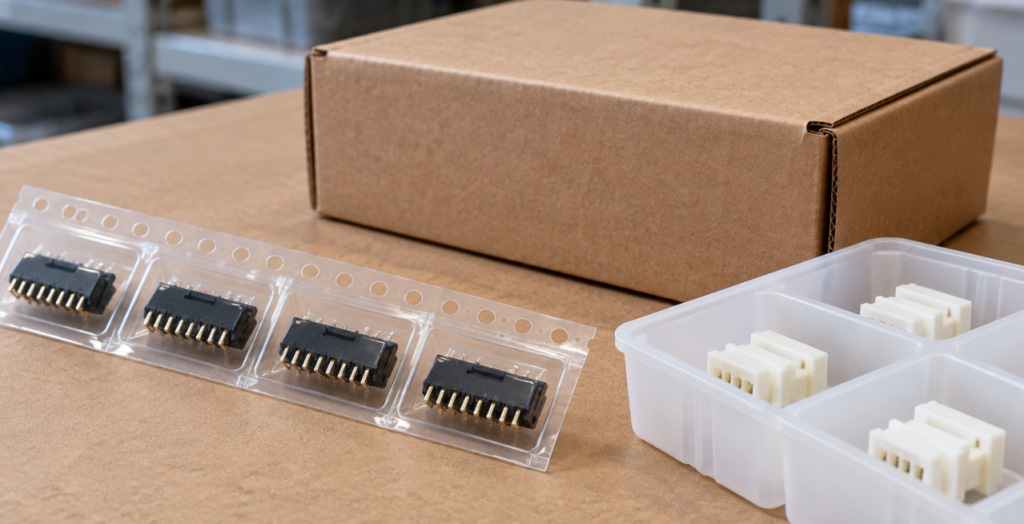
Loose parts can arrive with damaged contacts or actuators. The wrong package can also disrupt automated assembly. Specify the format you need and clarify whether the material is in original manufacturer packaging or has been repacked.
Follow the handling guidance for the actual item. Different connectors don’t necessarily need identical storage arrangements.
Relying on a Family Name Instead of Conditions
Descriptions such as “waterproof,” “high-speed,” and “power connector” leave important questions unanswered. Ask for the specification covering the exact part and configuration. If a rating depends on a particular mate, cable, seal, or installation method, include that condition in the review.
Conclusión
Knowing the common electronic connector types makes it easier to narrow your search. Before ordering, check the full part number, the mating assembly, and the conditions behind the ratings. Those details help you avoid receiving parts that look right but can’t be used.
DuoLink Electronics is an independent electronic-component supplier supporting connector inquiries and BOM sourcing. You can send DuoLink your RFQ with the manufacturer, full part number, quantity, mating counterpart, application, and documentation requirements. If you’re considering an alternative, include the original drawing and the properties your engineering team needs to approve.
Preguntas frecuentes
What are the main electronic connector types?
Common types include board-to-board, wire-to-board, wire-to-wire, pin headers and sockets, FFC/FPC, terminal blocks, circular, RF, and external interface connectors. Power connectors can belong to several of these categories.
Can connectors with the same pitch and pin count be interchanged?
You can’t tell from those details alone. Compare contact geometry, keying, retention, footprint, ratings, and the manufacturer’s mating references. If the match is uncertain, review drawings and samples before approving it.
Are terminals included when I order a connector housing?
Not always. Many systems sell housings, contacts, headers, and seals separately. Ask what’s included and list every required part number in the order.
Does a USB Type-C connector guarantee fast data or high-power charging?
No. Type-C alone doesn’t establish those capabilities. Check the receptacle, cable, controller implementation, and supported power arrangement against your product requirements.
What should I provide when requesting a connector quotation?
Send the manufacturer, full part number, quantity, packaging requirement, and mating counterpart. If you want an alternative, include drawings, cable or wire details, application requirements, and approval criteria.


 Spanish
 English
 German
 French
 Chinese
 Italian