
When purchasing optoelectronic components, the common problem is not the inability to find the product, but choosing a “similar-looking” model. LEDs of the same color may have different wavelengths and emission angles, and photodiodes of the same package may also have significant differences in response rate, photosensitive area, speed, and actual application environment.
I’m Lori. In the field of electronic component distribution and procurement, I have come across many such selection requirements. When we check the optoelectronic materials here, we do not just look at the product name or package size. The optical path where the device is located, the driving current, the operating temperature, response time, and the actual application environment usually need to be considered together.
This article will start from the working principle of optoelectronics, introduce you to common light-emitting, detection, isolation and communication devices, and explain the issues that engineers and procurement personnel need to pay attention to in selection, substitution and quality inspection.
1. What Is Optoelectronics?
Definition of Optoelectronics
Optoelectronics is a field of electronics concerned with devices that generate, detect, transmit, or control light. These devices create a working link between optical energy and electrical energy.
The light involved is not limited to the visible range. Optoelectronic systems may operate with ultraviolet, visible, infrared, or near-infrared radiation. The required wavelength depends on the device material and its intended function.
Most optoelectronic components perform one of three jobs:
| Conversion function | What happens | Common components |
|---|---|---|
| Electrical to optical | Electrical energy produces light | LEDs, laser diodes, infrared emitters, OLEDs |
| Optical to electrical | Incoming light produces an electrical response | Photodiodes, phototransistors, image sensors, solar cells |
| Optical transfer or control | Light carries or controls a signal within a system | Optocouplers, optical switches, fiber-optic transceivers |
This definition gives a practical answer to “What is optoelectronics?” It is not one product category with one operating principle. It is a group of technologies built around the interaction between photons and semiconductor materials.
How Optoelectronic Devices Work
In an LED or laser diode, an applied current causes electrons and holes to recombine inside a semiconductor junction. This releases energy as photons. The semiconductor material and device structure influence the wavelength, efficiency, output power, and beam characteristics.
A photodetector works in the opposite direction. Photons enter a light-sensitive semiconductor region and transfer energy to charge carriers. The resulting current or voltage can be measured and processed by the circuit.
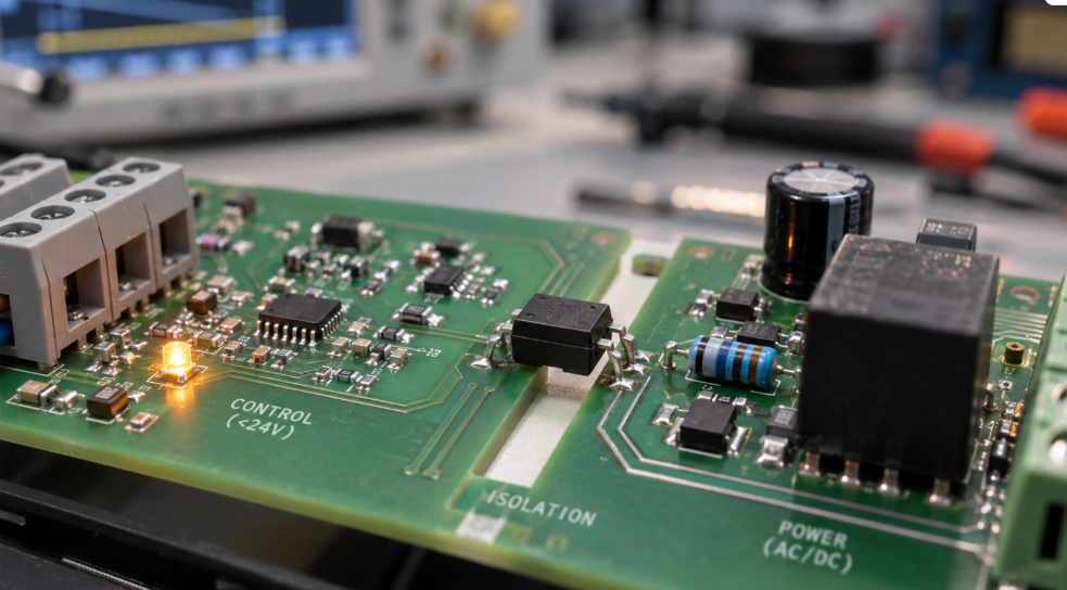
Optocouplers combine both actions in one package. An internal LED emits light, and a photodetector receives it across an electrically insulating gap. The signal crosses the gap, but direct electrical current does not. This arrangement helps protect low-voltage control circuitry from high-voltage sections, voltage spikes, and ground potential differences.
Optoelectronics vs. Photonics
Optoelectronics and photonics overlap, but they are not exact substitutes.
Optoelectronics usually focuses on semiconductor devices that convert signals between electrical and optical forms. LEDs, laser diodes, photodiodes, optocouplers, and optical sensors fit naturally within this field.
Photonics has a wider scope. It covers the generation, movement, processing, and measurement of light, including technologies that may not rely on electrical conversion at every stage. Optical fibers, lenses, waveguides, modulators, filters, and laser systems can all fall under photonics.
A useful way to separate them is to look at the system boundary. If the main concern is the electrical interface of a light-based semiconductor device, optoelectronics is usually the more precise term. If the design centers on how light travels or is manipulated as light, photonics may be the better description.
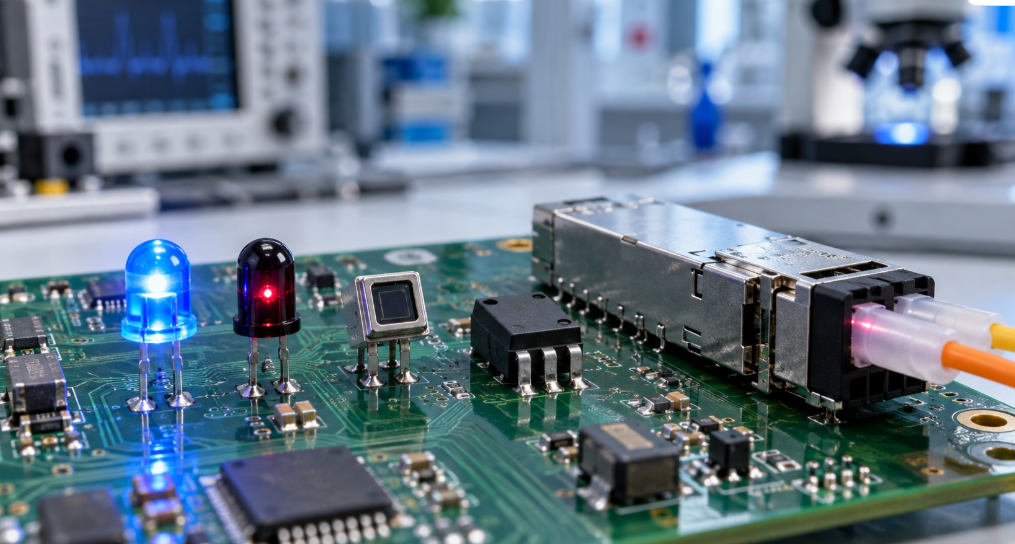
2. Main Components of an Optoelectronic System
Light-Emitting Components
A light-emitting component converts electrical energy into optical output. The correct choice depends on more than brightness.
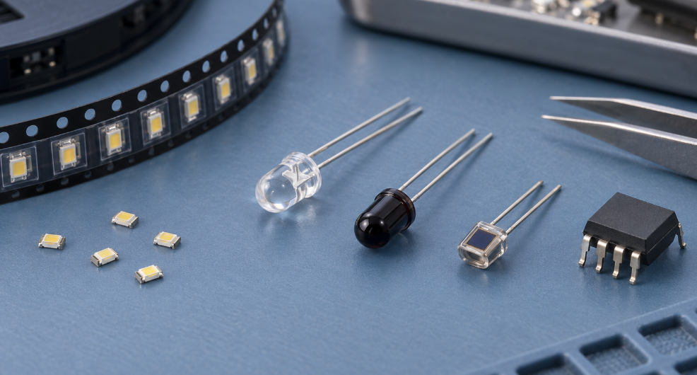
LEDs produce relatively broad-spectrum light and are available in many colors, packages, power levels, and viewing angles. They are widely used for indicators, illumination, displays, sensing systems, and optical signaling.
Laser diodes produce a narrower, more directional beam. Their optical output can be modulated at high speed, which makes them suitable for fiber communication, scanning, ranging, and precision sensing. They normally require tighter current control and thermal management than standard indicator LEDs.
Infrared emitters generate light outside the visible range. You will find them in remote controls, security systems, optical encoders, proximity sensors, and machine-vision lighting.
OLED devices use organic semiconductor layers to produce light. Since each pixel can emit its own light, OLED technology supports thin displays, high contrast, and flexible form factors.
Light-Detecting Components
Photodiodes generate a current related to the amount of incident light. They can provide fast response, predictable behavior, and low noise when matched with a suitable amplifier circuit.
Phototransistors include internal transistor gain. They can produce a stronger output than a basic photodiode, but that gain often comes with slower switching and less linear behavior. They work well in many presence-detection and switching applications where extreme speed is not required.
Photoresistors change resistance as light levels change. They are easy to use for basic light sensing, though their response is slower and their characteristics may vary with temperature and device history.
CMOS and CCD image sensors contain large arrays of light-sensitive pixels. CMOS sensors integrate more readout and processing functions on the chip and dominate many modern imaging applications. CCD sensors remain useful in selected scientific and measurement systems where particular noise or image-quality characteristics are valued.
Optical Control and Isolation Components
Optocouplers transfer signals across an isolation barrier. Their input and output characteristics must be evaluated together. A high isolation voltage does not guarantee that the output will switch correctly under every combination of input current, temperature, and device age.
Optical switches use a light source and detector to identify an interruption or reflection. Slotted switches can detect a moving flag or encoder wheel. Reflective switches monitor light returned from a nearby surface.
Solid-state relays often use an internal optical link to control a semiconductor output stage. They offer quiet operation and no mechanical contact wear, though leakage current, on-resistance, load type, and thermal behavior still need attention.
Fiber-optic transceivers contain transmitting and receiving functions for communication over optical fiber. Their selection may involve data rate, wavelength, connector format, fiber type, link distance, digital interface, power consumption, and standards compatibility.
3. Common Types of Optoelectronic Devices
LEDs and Laser Diodes
LEDs and laser diodes both produce light through semiconductor recombination, but their optical behavior is different.
| Selection factor | LED | Diode laser |
|---|---|---|
| Optical spectrum | Relatively broad | Narrow |
| Beam pattern | Wider and less directional | Narrow and directional |
| Coherence | Faible | Élevé |
| Modulation speed | Suitable for many indicators and short-range links | Better suited to high-speed links and precision optical systems |
| Drive requirements | Often less demanding | Requires controlled current and stronger thermal protection |
| Typical uses | Lighting, displays, status indicators, infrared controls | Fiber links, LiDAR, scanning, measurement |
Do not select either device from a color name alone. A “red LED,” for example, can be offered in several peak or dominant wavelengths. Its luminous intensity also depends on viewing angle. A narrow-angle LED may show a higher candela rating than a wide-angle version while producing a similar total light output.
Laser diode procurement needs extra care. Maximum optical power, threshold current, operating current, monitor photodiode configuration, polarity, package geometry, and cooling conditions all matter. Exceeding a transient current limit may damage the emitting region before a visible thermal problem appears.
Photodiodes, Phototransistors, and Optical Sensors
Detector selection starts with the light source. The detector must respond strongly enough at the source wavelength to create a usable signal.
Responsivity is normally expressed in amperes per watt and varies with wavelength. Sensitivity may refer to a broader system-level detection limit, so the two terms should not be treated as interchangeable. Dark current, noise, active area, reverse bias, junction capacitance, rise time, and amplifier design all influence the real result.
A larger photosensitive area can collect more light and make mechanical alignment easier. It may also increase junction capacitance and reduce response speed. A high-speed detector with a small active area might look better on a datasheet but perform poorly if the optical beam cannot remain aligned with it.
Le Hamamatsu silicon photodiode selection guide shows why spectral response, photosensitive area, and cutoff frequency need to be reviewed together. Buyers should request the full manufacturer datasheet rather than relying only on a distributor’s short product description.
Optocouplers and Optical Communication Devices
A standard optocoupler places an LED and a phototransistor, photodiode, logic gate, or triac driver in one package. Input current activates the emitter. Light crosses the internal barrier and controls the output.
For a phototransistor optocoupler, current transfer ratio, or CTR, is a key parameter. CTR describes the relationship between input LED current and output collector current under stated test conditions. It changes with temperature, input current, device variation, and operating age.
This is where replacement errors often occur. Two optocouplers may have the same pin count and isolation-voltage rating but different CTR bins, propagation delays, creepage distances, or output structures. A substitute can fit the PCB and still create unstable switching.
Optical communication devices add another layer of compatibility. A transceiver must match the system’s wavelength, fiber type, connector, data rate, electrical interface, link budget, and protocol requirements. The housing dimensions alone tell you very little about whether it can replace another module.
4. How Optoelectronic Components Convert Signals
Electrical-to-Optical Conversion
In a forward-biased light-emitting semiconductor junction, electrons and holes move into an active region. When they recombine, energy is released. Part of that energy leaves the device as photons.
The semiconductor bandgap influences photon energy and the resulting wavelength. Gallium nitride-based materials are commonly associated with blue and ultraviolet emitters, while gallium arsenide and related compounds support red and infrared devices.
Not all electrical input becomes useful light. Some becomes heat. Package construction, junction temperature, current density, and optical extraction efficiency affect the final output. For this reason, the specified test current and temperature must be checked when comparing LED brightness or laser output.
Optical-to-Electrical Conversion
A photodiode absorbs photons whose energy is sufficient to create electron-hole pairs in its semiconductor material. An internal electric field separates these carriers, producing photocurrent.
Material selection defines much of the usable spectral range. Silicon detectors are common for visible and near-infrared sensing. InGaAs devices extend sensitivity farther into the infrared and are often used in fiber communication and spectroscopy. Other materials serve ultraviolet, thermal infrared, or specialized detection requirements.
The complete receiver also matters. A photodiode may need a transimpedance amplifier to turn its small current into a usable voltage. Amplifier noise, feedback components, PCB leakage, ambient light, and shielding can limit performance even when the detector itself is correctly specified.
Signal Transmission and Electrical Isolation
Light can carry digital pulses, analog information, or modulated data without creating a conductive path between the transmitting and receiving sides.
In an isolated power supply, this can let the secondary-side feedback circuit communicate with a primary-side controller. In industrial automation, optical isolation may protect a control board from noisy motors, long cable runs, and differences in ground potential. You can see similar design needs across industrial automation electronics.
Isolation still depends on the complete design. Rated isolation voltage, working voltage, transient voltage, creepage, clearance, insulation class, and certification conditions are separate parameters. A high headline voltage should never replace a review of the datasheet and the safety requirements of the final equipment.
5. Major Applications of Optoelectronics
Consumer Electronics and Display Systems
Smartphones contain optoelectronic components in their screens, cameras, proximity sensors, ambient-light sensors, face-recognition systems, and optical communication functions.
Televisions and monitors use LEDs or self-emitting display technologies to create images. Remote controls use coded infrared pulses. Wearable devices may combine LEDs and photodiodes to measure changes in light passing through or reflected from tissue.
Camera performance also depends on more than the number of pixels. Pixel size, quantum efficiency, dynamic range, readout architecture, optical filters, lens alignment, and image-processing circuitry all shape the final image.
Industrial, Automotive, and Medical Equipment
Industrial equipment uses photoelectric sensors, encoders, safety light curtains, machine-vision systems, flame detectors, and isolated interfaces. The operating environment can be demanding. Dust, oil, vibration, electrical noise, and changing ambient light may alter system performance.
Vehicles use optoelectronics in lighting, rain sensors, cabin monitoring, optical communication, driver-assistance systems, and LiDAR. Parts intended for automotive designs may require qualified grades, controlled change processes, and extended temperature performance. The automotive electronics application overview provides more context on component requirements in vehicle systems.
Medical devices use LEDs, lasers, photodiodes, and image sensors in pulse oximeters, diagnostic analyzers, imaging equipment, patient monitoring, and therapeutic systems. Optical output stability and detector consistency may be just as important as initial accuracy. Procurement teams should also review traceability, regulatory documentation, lifecycle status, and change-notification requirements. These considerations are especially relevant when sourcing components for medical and healthcare electronics.
Communications, Energy, and Security Systems
Fiber-optic networks use laser emitters, photodetectors, and transceivers to move large amounts of data over long distances. Data centers depend on these links to connect switches, servers, and storage infrastructure.
Solar cells are optoelectronic devices on a larger scale. They absorb light and generate electrical power through the photovoltaic effect.
Security systems use infrared illumination, image sensors, optical barriers, and smoke or flame detectors. In such applications, the designer must account for ambient-light rejection, contamination, detector angle, expected target distance, and false-trigger conditions.
6. How to Select the Right Optoelectronic Component
Optical and Electrical Specifications
Start with the function the circuit must perform. Then build a parameter set around the real operating conditions.
| Paramètre | Ce qu'il faut vérifier | Common sourcing mistake |
|---|---|---|
| Wavelength | Peak, dominant, or detection range | Treating devices with the same color description as equivalent |
| Optical output | Luminous intensity, radiant intensity, flux, or optical power | Comparing values measured in different units or test conditions |
| Detector response | Responsivity, sensitivity, dark current, noise | Selecting from active area alone |
| Speed | Rise time, fall time, bandwidth, propagation delay | Ignoring the test load and bias conditions |
| Limites électriques | Forward voltage, drive current, reverse voltage, power | Designing around typical values instead of guaranteed limits |
| Geometry | Viewing angle, active area, lens shape, emitter-detector alignment | Checking the PCB footprint but not the optical path |
Luminous measurements are weighted to human vision. Radiometric measurements describe optical power without that visual weighting. An infrared emitter should normally be evaluated through radiant intensity or radiant power, not a visible-light brightness value.
Check minimum and maximum limits as well as typical figures. A typical value describes expected behavior under stated conditions, but it may not be guaranteed for every production unit.
Package, Environment, and Reliability
SMD packages support compact, automated assembly. Through-hole components may offer easier manual assembly, distinct optical positioning, or stronger lead retention in selected designs. Neither style is automatically better.
Review package dimensions, lead form, polarity, pinout, lens height, optical center, PCB land pattern, and reflow profile. Optical alignment can make a mechanically “close” replacement unusable.
Operating temperature needs equal attention. Light output, dark current, wavelength, CTR, and switching speed can shift as temperature changes. If the product will operate outdoors, in a vehicle, or near a heat source, room-temperature specifications are not enough.
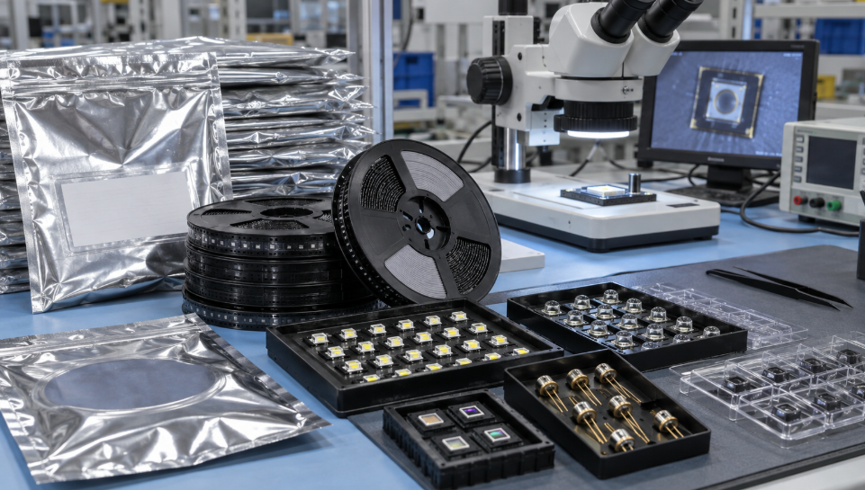
Moisture sensitivity affects storage and assembly of many surface-mount packages. For moisture-sensitive devices, confirm the MSL rating, packaging date, bag condition, humidity indicator card, desiccant, floor-life record, and any required baking instructions. Handling should follow the applicable manufacturer guidance and IPC/JEDEC J-STD-033.
ESD controls also matter. Optical semiconductor junctions can be damaged by electrostatic discharge without leaving obvious external marks. Proper packaging, grounded work areas, and controlled inspection procedures should continue from receipt through assembly.
Compatibility With the Complete Circuit
A component is only correct when it works inside the full optical and electrical system.
For an emitter, review the driver current, pulse conditions, thermal path, required optical output, viewing angle, lens, and target distance. For a detector, check the source wavelength, expected light level, optical filters, active area, bias circuit, amplifier, bandwidth, and noise budget.
Mechanical compatibility includes more than the footprint. The height of an emitter above the PCB can change alignment with a light pipe. A detector with a different lens shape may receive less reflected light. A replacement transceiver may fit the cage while using a different interface or fiber specification.
Before approving an alternate part, compare the schematic, PCB layout, optical structure, environmental conditions, and firmware thresholds. Prototype testing is still needed when the substitution affects signal level, timing, thermal behavior, or safety isolation.
7. Optoelectronic Component Sourcing and Quality Considerations
Manufacturer, Part Number, and Datasheet Verification
Use the complete manufacturer part number on the BOM and purchase order. Suffixes may identify package type, wavelength, color bin, output bin, CTR group, temperature grade, packing method, or qualification level.
Ask the supplier to confirm the manufacturer, exact part number, quantity, date or lot code when available, package, and traceability documents. Compare those details with the current manufacturer datasheet and product-status information.
A shortened part number creates room for error. The base number may describe a device family, while the missing suffix defines the version your design actually needs.
Compliance documents should be checked against the exact part, manufacturer, and revision. A general company statement is not the same as a part-level declaration. For products entering regulated markets, buyers can use the European Commission’s REACH Regulation information as a starting point for understanding chemical-substance obligations. The final compliance decision remains with the product manufacturer or responsible market operator.
Authenticity, Storage, and Inspection
Optoelectronic parts can carry risks that are not visible in a basic quantity check. These include incorrect labels, mixed lots, aged stock, damaged leads, opened moisture-barrier bags, contaminated optical surfaces, and inconsistent optical output.
Incoming inspection should match the risk level of the order. Packaging labels, manufacturer markings, dimensions, lead condition, reel information, and seal quality can be reviewed first. Higher-risk or hard-to-find material may justify electrical testing, optical testing, X-ray inspection, decapsulation, or laboratory analysis.
Optical testing must use controlled conditions. The light source, distance, angle, drive current, temperature, detector, and measurement equipment can all affect the result. Comparing readings taken from different setups may create a false failure or hide a real variation.
Storage records deserve attention as well. A sealed bag does not prove that the device was always stored correctly. Check whether moisture protection, ESD controls, and environmental conditions remained suitable throughout the supply chain.
BOM Sourcing and Alternative Component Evaluation
When an optoelectronic part is unavailable, obsolete, or subject to a long lead time, the safest replacement process begins with its function in the circuit.
Compare the optical specifications first: wavelength, spectrum, output or responsivity, beam pattern, active area, and optical geometry. Then review electrical ratings, timing, package dimensions, pinout, temperature range, qualification status, expected life, and regulatory documentation.
Package and basic voltage ratings are not enough. An LED substitute with a different viewing angle can create an uneven display. A photodiode with higher capacitance can reduce receiver bandwidth. An optocoupler with a lower guaranteed CTR may stop switching at the circuit’s minimum input current.
Engineering approval should be recorded before the alternative enters production. Samples can then be tested under low and high supply voltage, temperature limits, optical misalignment, aging conditions, and relevant load states.
Conclusion
Optoelectronics covers the components and systems that connect light with electrical signals. LEDs and laser diodes create light. Photodiodes and image sensors detect it. Optocouplers and fiber devices use light to transfer information, provide isolation, or support high-speed communication.
The core selection rule is to evaluate the complete signal path. Wavelength, optical output, responsivity, speed, circuit conditions, package geometry, temperature, storage, and lifecycle status all need to work together. A part that looks compatible in a catalog may behave very differently once it reaches the PCB.
If you are sourcing electronic components, Duolink Electronics is an independent electronic components supplier offering integrated circuits, semiconductors, passive components, connectors, optoelectronic devices, and other electronic parts. Our team supports BOM sourcing, part-number inquiries, inventory checks, and hard-to-find component sourcing. Leave a message through our website if you have a component requirement you would like us to review.
Foire aux questions
What information should I provide when requesting an optoelectronic component?
Provide the full manufacturer part number, required quantity, target delivery time, application, package, and any mandatory qualification or compliance requirements. If alternatives are acceptable, include the optical and electrical parameters that cannot change.
Can an LED with the same color and package replace the original part?
Not automatically. Compare dominant or peak wavelength, luminous or radiant output, viewing angle, forward voltage, drive current, polarity, lens geometry, temperature performance, and binning conditions.
What should be checked when sourcing older optoelectronic stock?
Check the date or lot code, packaging condition, MSL status, storage history, ESD protection, lead condition, optical-surface cleanliness, traceability, and current manufacturer lifecycle status.
How should a replacement photodiode be evaluated?
Match its spectral response to the light source, then compare responsivity, active area, dark current, capacitance, noise, response time, reverse-voltage rating, package, and optical alignment. Test it with the actual receiver circuit.
Is the isolation-voltage rating enough to select an optocoupler?
No. You should also review working voltage, creepage, clearance, insulation type, CTR or output configuration, propagation delay, input-current range, temperature behavior, safety approvals, and package dimensions.


 French
  English
  German
  Spanish
  Chinese
  Italian