
In the procurement of relays, confirming the coil voltage and contact current is only the first step. I’m Lori. With years of experience in component procurement and supply, I have discovered that many relay problems do not stem from the components themselves, but rather from not accurately representing the actual load conditions during the selection process.
A relay with a nominal capacity to handle a relatively high current may not be able to operate stably for a long time when facing motors, LED drivers, or transformers. The current and voltage changes generated by these loads during startup or disconnection are often much higher than the data seen during normal operation.
Next, we will explore each type of relay: electromechanical, solid-state, reed, latch, delay, thermal overload, automotive, signal, power, and safety. You can review the working characteristics of each structure and then narrow down the selection range based on the load, lifespan, environment, and safety requirements.
| Relay type | Main strength | Typical applications | Key selection concern |
|---|---|---|---|
| Electromechanical | Flexible contact arrangements | Appliances, control panels, alarms | Mechanical and electrical life |
| Solid-state | Fast, silent switching | Heaters, automation, process control | Leakage current and heat |
| Reed | Clean low-level switching | Test equipment, instruments, medical circuits | Contact sensitivity |
| Latching | Holds its state without continuous coil power | Smart meters, battery devices | Reset method and pulse control |
| Time-delay | Switches after a defined time | Motor sequencing, lighting, ventilation | Timing mode and range |
| Thermal overload | Protects motors against sustained overload | Pumps, compressors, conveyors | Trip class and motor current |
| Automotive | Designed for vehicle conditions | Lighting, fans, pumps, vehicle ECUs | Temperature, vibration, DC arcing |
| Signal | Handles low-current electronic signals | Telecom, measurement, control boards | Contact resistance and isolation |
| Power | Switches higher load current | Appliances, chargers, energy systems | Inrush current and endurance |
| Safety | Supports monitored protective functions | Emergency stops, safety doors, machinery | Architecture and safety compliance |
1. Electromechanical Relays: Versatile Switching for General Circuits
How Electromechanical Relays Operate
An electromechanical relay, commonly called an EMR, uses a coil to produce a magnetic field. The field moves an armature, which opens or closes one or more physical contacts. When coil power is removed, a spring normally returns a non-latching relay to its original position.
Common contact arrangements include SPST, SPDT, DPST, and DPDT. Designers may also describe contacts as Form A, Form B, or Form C. These configurations affect how many circuits the relay can control and what happens when the coil is not energized.
The coil circuit and load circuit remain electrically isolated. That makes an EMR useful when a low-voltage control board must switch a separate AC or DC load.
Common Applications in Industrial Controls and Consumer Electronics
Electromechanical relays appear in industrial control panels, security systems, household appliances, HVAC equipment, lighting controls, and power distribution boards. They work with many load types and can provide normally open and normally closed contacts in a compact package.
A control system may use the relay as an interface between a microcontroller and a solenoid, pump, lamp, or contactor coil. For broader system-level component considerations, the applicazioni di automazione industriale page shows how switching devices fit into control and monitoring equipment.
Main Advantages and Mechanical Limitations
The main strengths are galvanic isolation, low off-state leakage, visible contact configurations, and the ability to switch AC or DC loads. The physical contact gap can also provide clear circuit separation.
Moving parts introduce contact bounce, audible noise, and mechanical wear. Contact erosion becomes more severe when a load produces high inrush current or an inductive turn-off arc. A relay rated for 10 A under a resistive test condition should not automatically be treated as a 10 A motor relay.
Check electrical life at the actual voltage, current, load category, and switching frequency. Mechanical life only measures operation without the specified electrical load, so it should not be used as the expected service life of a loaded circuit.
2. Solid-State Relays: Fast Switching Without Moving Contacts
How Semiconductor-Based Relay Switching Works
A solid-state relay uses semiconductor devices rather than moving contacts. Depending on the output, it may contain a triac, thyristor, MOSFET, or transistor arrangement. An optocoupler is often used to separate the control side from the load side.
AC SSRs may offer zero-cross switching, which turns the load on near the point where the AC waveform crosses zero. Random-turn-on versions respond without waiting for that crossing and are used when phase control or precise timing is required.
DC SSRs require attention to polarity and output topology. Back-to-back MOSFET designs can switch signals in both directions, while a single-MOSFET output may be suitable only for one current direction.
Applications in Heating, Automation, and Motor Control
SSRs are widely used for resistive heaters, ovens, packaging machinery, process controls, lighting systems, and high-cycle automation. Their silent operation and lack of contact bounce suit equipment that switches frequently.
They can control some motors and solenoids, but the SSR must be selected for the exact load. A general-purpose resistive-load SSR may not tolerate motor starting current or the voltage transient created when an inductive load is disconnected.
Leakage Current, Heat Dissipation, and Load Compatibility
An SSR is not a perfect open circuit when off. A small leakage current can pass through the output, which may cause an LED lamp to glow faintly or a sensitive load to remain partly energized. It also develops an on-state voltage drop, producing heat during operation.
Review the thermal resistance, ambient temperature, mounting method, heat-sink requirement, and derating curve together. The usable current can be much lower than the headline rating when the SSR operates inside a warm enclosure. The manufacturer’s technical guidance for solid-state relay load behavior also shows why inrush characteristics must be evaluated by load type.
3. Reed Relays: Reliable Switching for Low-Level Signals
Reed Contact Structure and Operating Principle
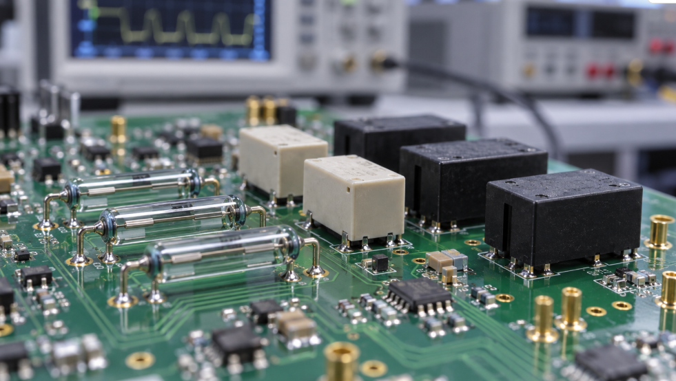
A reed relay contains thin ferromagnetic contact blades sealed inside a glass tube. Energizing the surrounding coil magnetizes the blades and causes them to make or break contact.
The sealed construction protects the switching surfaces from dust, moisture, and many atmospheric contaminants. Low moving mass allows relatively fast operation, while the compact contact structure can provide low capacitance and good isolation.
Applications in Test Equipment, Medical Devices, and Communication Circuits
Reed relays are used in automatic test equipment, data acquisition systems, measurement instruments, telecommunications hardware, sensor interfaces, and selected medical electronics. They are particularly useful when the circuit carries a low-level analog or digital signal rather than substantial power.
In medical and precision measurement designs, the engineer may care more about insulation resistance, thermal EMF, contact resistance stability, and channel density than about a large current rating. You can review the wider component environment on the medical and healthcare electronics applications pagina.
When to Choose a Reed Relay Over a Standard Electromechanical Relay
Choose a reed relay when the priority is small size, fast response, low signal disturbance, high insulation resistance, or a sealed contact system. A conventional EMR is usually more suitable when you need higher load capacity, broader contact arrangements, or stronger tolerance for general power switching.
Do not assume that a reed relay can safely switch a load merely because the steady-state current is low. Capacitive loads can produce a short charging surge, while inductive loads can create a high release voltage. Both conditions can damage delicate reed contacts.
4. Latching Relays: Maintaining Contact Position With Minimal Power
Single-Coil and Dual-Coil Latching Designs
A latching relay retains its last contact position after the control signal is removed. It does not require continuous coil power to maintain that state.
A single-coil version normally changes state according to pulse polarity. A dual-coil version uses one coil to set the relay and another to reset it. The exact pulse duration, polarity, and coil connection must follow the datasheet.
Applications in Smart Meters, Energy Management, and Battery-Powered Devices
Latching relays are common in smart meters, energy control units, battery-operated equipment, access systems, and remote switching products. Their low holding-power requirement reduces heat and supports energy-efficient designs.
They are also useful when the circuit must preserve its switching state after a temporary loss of control power. That behavior must be intentional. A retained state can create an unexpected restart condition if the system firmware assumes every relay returns to a default position.
Reset Requirements and Circuit Design Considerations
The control circuit needs a defined set-and-reset strategy. During startup, the controller may not know the relay’s physical position unless it stores the previous state or receives contact feedback.
Check the minimum and maximum pulse width, coil energy, drive polarity, and simultaneous-coil restrictions. A pulse that is too short may not complete the movement. A pulse held for too long can overheat a coil designed for momentary operation.

5. Time-Delay Relays: Controlling When a Circuit Switches
On-Delay, Off-Delay, and Interval Timing Functions
A time-delay relay combines a timing circuit with a switching output. An on-delay relay waits for the selected period before changing its contacts. An off-delay unit keeps the output active for a defined period after the control signal changes. An interval timer activates the output for a preset window.
Some products provide multifunction timing, while others support only one operating mode. The trigger input, supply input, and output contact may also be arranged differently across product families.
Applications in Motor Sequencing, Lighting, and Industrial Automation
Time-delay relays control staged motor starting, fan run-on, pump sequencing, lighting, compressor protection, alarm delays, and machine cycles. They can perform local timing without requiring a programmable controller.
Timing accuracy should match the process. A ventilation fan may tolerate a broad timing variation, while a coordinated machine sequence may require better repeatability and a narrower tolerance.
Selecting the Appropriate Timing Range and Operating Mode
Confirm whether the specified delay starts when power is applied, when a separate trigger arrives, or when that trigger is removed. This small detail causes many incorrect substitutions.
Review the timing range, repeat accuracy, reset time, supply-voltage tolerance, output contact rating, and behavior after a short power interruption. For motor-related circuits, verify whether the relay switches the motor directly or only controls a contactor coil.
6. Thermal Overload Relays: Protecting Motors From Excessive Current
How Thermal Overload Detection Works
A thermal overload relay is a motor-protection device rather than a general-purpose switching relay. Current flowing through its sensing elements generates heat. When a sustained overload raises the element temperature beyond the set level, the device trips and opens a control contact, which releases the motor contactor.
Thermal overload protection responds to the heating effect of excess current. It is not a replacement for short-circuit protection. Fuses or circuit breakers are still required to interrupt high fault current.
Electronic overload relays may measure current electronically and offer functions beyond the traditional bimetal design, including phase-loss detection, ground-fault monitoring, and adjustable trip behavior.
Applications in Motors, Pumps, Compressors, and Conveyor Systems
These relays protect three-phase motors in pumps, compressors, fans, conveyors, mixers, and machine tools. They are commonly paired with contactors in motor starters.
The device must match the motor and starting profile. A conveyor carrying a heavy load may take longer to accelerate than a lightly loaded fan. Selecting an overly fast trip response can cause nuisance shutdowns even when the motor is operating as designed.
Current Setting, Trip Class, and Reset Mode Considerations
Base the current setting on the motor nameplate and the manufacturer’s coordination instructions. Do not size it only from the contactor frame or upstream breaker rating.
Trip class describes how quickly the relay responds under defined overload conditions. The correct class depends on motor starting time and thermal tolerance. You should also choose between manual and automatic reset carefully. Automatic reset may be unacceptable where an unexpected motor restart could place personnel or machinery at risk.
7. Automotive Relays: Managing Electrical Loads in Vehicles
Construction Requirements for Automotive Environments
Automotive relays are designed for electrical noise, vibration, shock, temperature cycling, moisture, and contaminated environments. Many operate from nominal 12 V or 24 V systems, but the actual vehicle supply can experience cranking dips and transient overvoltage.
Sealed construction may be needed, yet the word “sealed” must be interpreted through the manufacturer’s process and test definitions. It does not automatically mean that a relay can be mounted anywhere in a vehicle or exposed directly to water.
Applications in Lighting, Fans, Fuel Pumps, and Electric Vehicles
Automotive relays switch headlamps, cooling fans, fuel pumps, horns, heated windows, seat systems, compressors, and auxiliary loads. Electrified vehicles also use specialized relays and contactors in charging, battery management, and high-voltage power distribution.
The load profile matters. A cold lamp filament, stalled fan motor, or capacitive electronic module may draw several times its normal operating current when first energized.
Voltage, Current, Temperature, and Vibration Requirements
Ask for the relay’s DC switching data at the intended system voltage. DC arcs do not benefit from the natural zero crossing found in AC circuits, so contact opening distance and arc-control design carry more weight.
Check operating temperature, vibration test conditions, terminal style, coil suppression, mounting direction, contact material, and approved load curve. Safety-related vehicle electronics may also fall within an ISO 26262 functional-safety development framework, but using an automotive relay does not make the complete system compliant. The system architecture, diagnostics, development process, and verification evidence must support that claim.
More application-focused considerations are available in the applicazioni nell'elettronica automobilistica overview.

8. Signal Relays: Switching Low-Current Electronic Signals
Contact Sensitivity and Signal Integrity
Signal relays are designed to switch low-current and low-voltage circuits. They are commonly built with small contacts, compact coils, and contact materials selected for stable low-level performance.
A large power relay may appear electrically capable of handling a tiny signal, but its contacts may depend on sufficient current to break through surface films. This can make the contact resistance unstable when used far below the intended load range.
Applications in Telecommunications, Measurement, and Control Boards
Signal relays route analog channels, communication lines, alarm circuits, sensor outputs, test points, and control-board signals. Common environments include telecom equipment, laboratory instruments, building controls, and automatic test systems.
For high-frequency or precision signals, examine parasitic capacitance, crosstalk, insulation resistance, and bandwidth. The relay’s basic on/off function is only one part of the signal path.
Contact Resistance, Insulation, and PCB Footprint Considerations
Look for minimum applicable load data, not only maximum current. Check initial contact resistance and whether the datasheet defines its measurement method. A low published value does not guarantee that resistance will remain unchanged throughout the operating life.
PCB layout should maintain the isolation distance required by the end product. Pin-compatible relays can still differ in height, coil polarity, internal suppression, contact arrangement, or creepage performance.
9. Power Relays: Controlling High-Current Electrical Loads
Differences Between Signal Relays and Power Relays
Power relays use contact structures, terminals, and arc-management features intended for higher load current. They may have larger contact gaps, stronger springs, wider conductive paths, or materials chosen to resist welding and erosion.
“Power relay” is a broad label, not a complete specification. Some are optimized for AC appliances, while others target DC charging, solar equipment, energy storage, or industrial control.
Applications in Power Supplies, Appliances, Chargers, and Energy Systems
Power relays are found in power supplies, air-conditioning units, household appliances, uninterruptible power systems, EV chargers, solar inverters, battery equipment, and industrial machines.
They may switch the primary input, bypass path, pre-charge circuit, heating element, compressor, or output load. Each position exposes the contacts to a different electrical stress.
Contact Ratings, Inrush Current, and Electrical Endurance
Start with the load waveform. A heater behaves mainly as a resistive load. A motor has starting and stall current. A power supply input can draw a short capacitive surge. A transformer may produce an inrush peak based on the switching phase and residual core flux.
| Load type | Main relay stress | Cosa verificare |
|---|---|---|
| Resistive heater | Continuous current and heat | Current rating at operating temperature |
| Motor or compressor | Starting and stall current | Motor-load rating and endurance curve |
| LED driver or power supply | Capacitor charging surge | Peak current, duration, and contact welding resistance |
| Solenoid or contactor coil | Inductive turn-off voltage | Suppression method and DC load rating |
| Transformer | Magnetizing inrush | Approved transformer load or tested waveform |
| Battery or DC bus | Sustained DC arc | DC voltage, polarity, contact gap, breaking capacity |
Check both electrical endurance and mechanical endurance. Electrical life should be supported by test conditions close to your actual load. If the datasheet does not cover the application, request guidance or perform representative load testing before approving the design.
When sourcing from a relay product category, provide the manufacturer part number whenever possible. If you need an alternative, include the full load profile rather than supplying only the coil voltage and current rating.
10. Safety Relays: Supporting Reliable Machine Protection
Force-Guided Contacts and Fault-Detection Functions
The term “safety relay” can refer to a relay with forcibly guided contacts or a complete safety-monitoring module. These products are related but not interchangeable.
In a force-guided relay, normally open and normally closed contacts are mechanically linked so they cannot occupy conflicting closed states under specified fault conditions. This arrangement allows an external circuit to detect certain contact failures, such as a welded contact. IEC 61810-3 addresses elementary relays with forcibly guided, mechanically linked contacts.
A safety relay module may include dual-channel inputs, monitored reset, cross-fault detection, internal redundancy, and controlled safety outputs. Its behavior depends on the full internal design, not merely the presence of one specialized relay.
Applications in Emergency Stops, Safety Doors, and Industrial Machinery
Safety relays monitor emergency-stop buttons, guard-door switches, light curtains, two-hand controls, pressure-sensitive devices, and other machine protection inputs. When the safety function is requested or a monitored fault is detected, the outputs remove energy from the controlled hazard through the designed shutdown path.
The relay must be integrated with suitable sensors, output devices, wiring, diagnostics, and reset logic. A high-performance safety relay cannot compensate for a single-channel circuit where the required risk assessment calls for redundancy.
Safety Standards, Contact Configuration, and System Integration
Begin with the machine risk assessment and required safety function. Then evaluate the module’s supported architecture, performance level or safety integrity capability, contact configuration, response time, diagnostic coverage, supply voltage, reset type, and feedback-loop arrangement.
Never approve a substitution based only on matching terminal count. A different unit may change input test pulses, short-circuit detection, reset behavior, contact timing, or achievable safety level.

How to Select the Right Relay for Your Application
Relay selection should begin with the real electrical and environmental conditions, not the category name alone. Before requesting a quotation or approving a substitute, prepare the following information:
- Manufacturer and exact part number, if already specified
- Coil or input voltage, including tolerance
- AC or DC load voltage
- Normal current, starting current, and possible fault current
- Resistive, inductive, capacitive, lamp, motor, or transformer load
- Required contact form and number of poles
- Expected switching cycles per hour and total operating life
- Ambient temperature and enclosure conditions
- PCB, socket, panel, or plug-in mounting
- Isolation, creepage, clearance, or safety requirements
- Applicable automotive, industrial, medical, or environmental standards
- Required documentation, traceability, date code, and packaging
This information prevents a common sourcing mistake: finding a relay that fits the footprint but does not fit the load. For regulated markets, purchasing teams may also need material declarations related to the EU RoHS framework or substances covered by ECHA’s REACH guidance. Ask for part-specific documentation and verify the document revision instead of assuming compliance from the brand name.
Conclusione
The top 10 types of relays and their applications cover very different switching and protection needs. Electromechanical relays offer broad flexibility. Solid-state relays suit frequent, quiet operation. Reed and signal relays protect low-level signal quality. Latching types reduce steady power demand. Time-delay and thermal overload relays perform specialized control or protection functions. Automotive, power, and safety relays address harsher electrical or operational requirements.
The core selection decision still comes back to the load. Coil voltage and nominal contact current are only the starting points. Inrush behavior, DC breaking ability, switching frequency, temperature, contact material, electrical endurance, isolation, and regulatory requirements determine whether the relay will operate reliably in the finished product.
If you are sourcing electronic components, DuoLink Electronics is an independent distributor supplying integrated circuits, semiconductors, passive components, connectors, relays, and other electronic parts. Our team supports BOM sourcing, part-number searches, inventory checks, and hard-to-find component procurement. You can Contatta DuoLink Electronics through the website with your BOM or technical requirements.
Domande frequenti
Can I replace a relay with another part that has the same coil voltage and contact rating?
Not safely from those two values alone. Compare the contact form, pinout, coil resistance, load type, inrush capacity, DC or AC rating, operating temperature, isolation, dimensions, and electrical life.
Why does a relay fail even when the load current is below its rated current?
The load may have a starting surge or turn-off transient far above its steady current. High switching frequency, poor heat dissipation, contact bounce, incorrect suppression, and operation outside the stated temperature range can also shorten relay life.
Can an AC-rated relay switch the same voltage and current in DC?
Do not assume it can. DC arcs are harder to extinguish because the current has no natural zero crossing. Use the manufacturer’s DC load curve or a relay specifically rated for the required DC voltage and current.
What information should I provide when requesting a relay substitute?
Provide the original part number, coil voltage, contact form, pinout, mounting style, load voltage, steady current, inrush current, load type, operating temperature, required approvals, and expected switching life.
Should I choose an electromechanical relay or a solid-state relay?
Choose according to the load and operating pattern. An EMR offers physical contacts, very low off-state leakage, and broad load flexibility. An SSR offers silent, fast, high-cycle switching but needs checks for leakage current, heat dissipation, and load compatibility.


 Italian
  English
  German
  Spanish
  French
  Chinese