If you are reviewing a BOM, you might find that the name of the inductor is more complicated than you expected. Ferrite Core, Wire-Wound, Molded, Shielded and RF Choke often appear together in the datasheet. Some describe the structure, some describe the material, and some indicate the specific application.
I’m Lori. In the field of electronic component distribution and procurement, I usually don’t judge whether an inductor is suitable just based on its name. The core thing is to see if it can maintain stable performance under actual current, frequency and temperature conditions.
Next, we will introduce ten common types of inductors in electronic circuits, clarify the differences and connections between them, and explain which circuits each product is more suitable for.
1. Air Core Inductors
How Air Core Inductors Work
An air core inductor has no ferromagnetic core. Its copper winding may be self-supporting or formed around ceramic, plastic, or another non-magnetic material. Since there is no magnetic core to concentrate the flux, its inductance mainly depends on the number of turns, coil diameter, winding length, and spacing between turns.
“Air core” describes the magnetic path, not necessarily an empty physical center. A ceramic former, for instance, can support the winding without behaving like a ferrite core.
Main Advantages and Limitations
Air core inductors avoid magnetic saturation and most core-related losses. They can maintain a high Q factor and stable behavior at radio frequencies when their geometry is properly controlled. Their self-resonant frequency can also be higher than that of many magnetic-core alternatives.
The trade-off is lower inductance for a given physical size. Producing more inductance requires additional turns or a larger coil, which adds resistance and parasitic capacitance. Air core components are rarely the first choice when a compact circuit must store substantial energy.
Common Circuit Applications
These inductors are commonly used in RF impedance-matching networks, oscillators, antenna circuits, high-frequency filters, and wireless communication equipment. Their predictable high-frequency behavior is often more useful than a high nominal inductance value.
2. Ferrite Core Inductors
What Is a Ferrite Core Inductor?
A ferrite core is made from ceramic magnetic material containing iron oxide combined with other metallic elements. Its relatively high magnetic permeability concentrates magnetic flux and allows a coil to produce more inductance with fewer turns.
Ferrite also has high electrical resistivity. This limits eddy-current losses compared with electrically conductive magnetic materials, making ferrite suitable for many switching and high-frequency applications.
Ferrite Material and Frequency Range
Ferrite is not one uniform material. Different formulations produce different permeability, saturation flux density, temperature behavior, and loss characteristics.
Manganese-zinc ferrites are often selected for lower-frequency power conversion, where permeability and energy handling matter. Nickel-zinc materials have higher resistivity and are commonly used at higher frequencies, including EMI suppression and RF applications.
A part described only as a “ferrite inductor” still needs closer review. Check the manufacturer’s loss curves, DC-bias behavior, test frequency, operating temperature, and intended application. Two ferrite inductors with the same inductance and package size can behave quite differently under load.
Common Circuit Applications
Ferrite core inductors appear in switching power supplies, noise filters, power rails, communication equipment, consumer electronics, and signal lines. They are also widely used in ferrite beads and common-mode suppression components.
3. Iron Powder Core Inductors
Construction of Iron Powder Inductors
An iron powder core is formed by pressing small iron particles together with an insulating binder. Each particle is electrically insulated from the surrounding particles. This structure reduces large circulating currents inside the core while creating many tiny gaps throughout the magnetic path.
The result is called a distributed air gap.
Distributed Air Gap and Saturation Performance
A distributed gap lets the core store magnetic energy across its volume. It also creates a gradual change in inductance under increasing DC bias. Instead of reaching a sharp saturation point, many iron powder inductors show a softer reduction in inductance as current rises.
This characteristic can be useful in power circuits exposed to steady DC current or temporary load peaks. The limitation is that iron powder can have higher core loss than a carefully selected ferrite material, especially as switching frequency rises.
Do not choose between ferrite and iron powder by current rating alone. Review core loss at the actual switching frequency, peak flux, ripple current, and operating temperature. A component that looks suitable at room temperature may run much hotter inside an enclosed power module.
Common Circuit Applications
Iron powder inductors are used in DC-DC converters, power factor correction circuits, output filters, industrial power supplies, and power modules. Toroidal iron powder parts also remain common in circuits that need energy storage with controlled saturation behavior.
4. Toroidal Inductors
Toroidal Core Structure
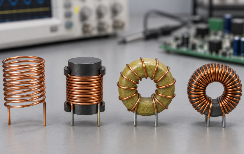
A toroidal inductor uses a ring-shaped magnetic core. The winding passes around the ring, creating a closed magnetic path inside the core.
“Toroidal” describes the component’s geometry. The core itself may be made from ferrite, iron powder, nanocrystalline material, or another magnetic alloy. Core material still determines much of the electrical performance.
Why Toroidal Inductors Reduce Magnetic Leakage
The closed path keeps a large portion of the magnetic flux inside the core. This can reduce leakage fields and unwanted coupling with nearby traces or components. The ring shape also uses core material efficiently and can support high-current windings.
Toroidal parts are not automatically free from EMI. Gaps between turns, uneven winding distribution, lead placement, and operation near saturation can increase stray fields. Their manufacturing process is also more involved because the wire must pass through the core repeatedly.
Common Circuit Applications
Toroidal inductors are found in mains filters, audio equipment, inverters, industrial control systems, output filters, and high-current power circuits. Their low leakage can be valuable where nearby analog or communication circuits are sensitive to magnetic coupling.
5. Wire-Wound Inductors
How Wire-Wound Inductors Are Manufactured
A wire-wound inductor is made by winding insulated copper wire around a magnetic or non-magnetic core. Depending on the product, the core may be ferrite, ceramic, iron powder, or magnetic composite material.
The winding may remain exposed, sit inside a drum core, receive an external magnetic shield, or become enclosed in a molded body. Wire diameter, turn spacing, termination design, and core shape all affect the final performance.
Electrical Characteristics
Wire-wound construction can provide low DCR because the manufacturer can use relatively thick copper wire. Lower winding resistance reduces conduction loss and voltage drop. This is one reason wire-wound parts are widely used in high-current power circuits.
The same structure can also deliver a high Q factor in RF products. More turns increase inductance, but they also increase resistance and interwinding capacitance. That capacitance lowers the self-resonant frequency.
TDK’s overview of inductor construction identifies wire-wound, multilayer, and thin-film products as three major manufacturing structures. It also notes that thick copper wire helps lower DCR in wire-wound components.
Common Circuit Applications
Wire-wound inductors support power conversion, RF networks, filters, automotive electronics, industrial equipment, and audio circuits. Before replacing one wire-wound part with another, compare its test frequency, DCR, saturation behavior, Q curve, and package footprint—not only its printed inductance.
6. Multilayer Chip Inductors
Internal Multilayer Construction
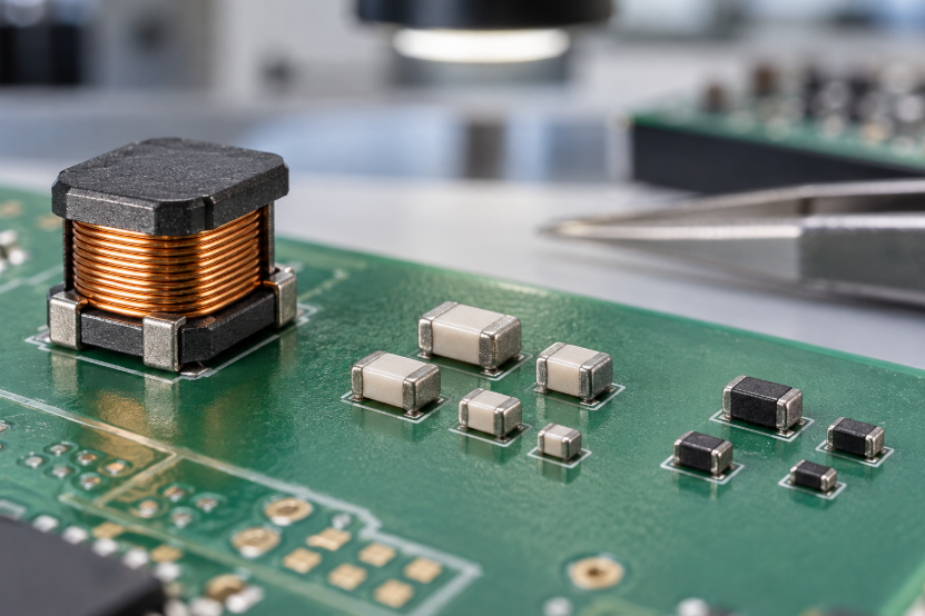
A multilayer chip inductor contains printed conductive patterns separated by thin layers of ceramic or ferrite material. During manufacturing, these layers are stacked, aligned, laminated, and fired to create a three-dimensional internal coil.
There is no conventional wire winding. The internal conductor pattern and material system define the inductance, resistance, and high-frequency response.
Benefits for Compact PCB Designs
Multilayer technology produces small, repeatable packages that are well suited to automated surface mounting. These inductors can fit into tightly packed boards where component height and footprint matter.
Their compact structure comes with limits. Narrow internal conductors may produce higher DCR than a larger wire-wound part. Current capacity and energy storage are also usually lower, although multilayer power-inductor designs continue to improve.
A purchasing team should verify the exact series rather than treating all 0402 or 0603 inductors as interchangeable. Parts that share the same package and nominal inductance may have different Q values, SRFs, impedance curves, tolerances, and DC-bias characteristics.
Common Circuit Applications
Multilayer chip inductors are widely used in smartphones, wearable devices, wireless modules, RF front ends, signal filters, and other compact electronics. Ferrite multilayer parts may also appear in low-power supply lines and noise-suppression networks.
7. Thin-Film Inductors
Thin-Film Manufacturing Technology
Thin-film inductors are produced through highly controlled processes such as material deposition, photolithography, plating, and precision conductor patterning. These methods form very small and consistent internal structures.
The technology gives manufacturers tight control over line width, spacing, film thickness, and geometry. That consistency is valuable in circuits where small parasitic differences can alter RF performance.
Precision and High-Frequency Performance
Thin-film inductors generally offer tight inductance tolerance, low parasitic variation, high self-resonant frequency, and repeatable impedance behavior. They work well when a design requires stable matching across many production units.
Their main limitation is power handling. Fine conductors and small packages restrict current capacity compared with larger wire-wound or molded power inductors.
At RF frequencies, the nominal inductance shown in the ordering code is only the starting point. Review Q versus frequency, impedance versus frequency, SRF, DCR, and the manufacturer’s recommended operating range.
Common Circuit Applications
Thin-film inductors are used in RF matching circuits, filter networks, communication modules, radio transceivers, and high-frequency circuits around wireless chipsets. They are often selected when repeatability and a controlled RF response matter more than energy storage.
8. Molded and Shielded Power Inductors
Molded Inductor Construction
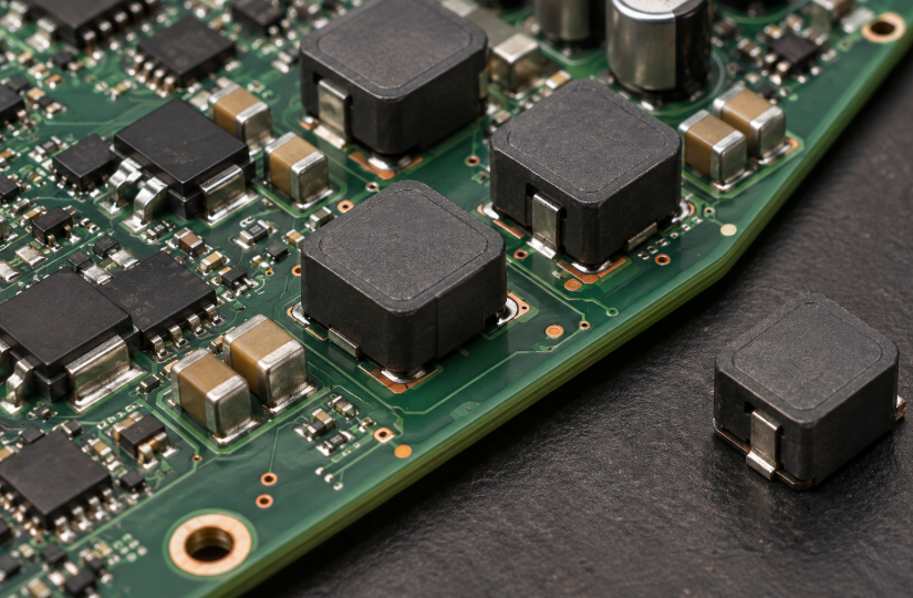
A molded power inductor usually places a copper winding inside magnetic composite material. The material surrounds much of the coil, producing a compact body with a distributed magnetic structure.
A fully shielded design directs more flux through the magnetic body and limits stray fields. A semi-shielded inductor may use a magnetic coating or partial enclosure. Semi-shielded parts can offer a useful balance of size and performance, but they usually allow more magnetic leakage.
The distinction should be confirmed in the manufacturer’s datasheet. Product titles do not always describe shielding in the same way.
Current Capacity, DCR, and EMI Performance
Four parameters deserve close attention:
| Parameter | What It Tells You | Common Purchasing Risk |
|---|---|---|
| Saturation current, Isat | Current at which inductance falls by a stated percentage | Different manufacturers may use different percentage limits |
| Temperature-rise current, Irms | Current that causes a defined temperature increase | Test board and airflow may differ from the finished product |
| DCR | Copper resistance under DC conditions | Maximum DCR may be higher than the typical value |
| Shielding | Ability to contain the magnetic field | “Shielded” does not guarantee equal EMI performance across series |
The usable current is normally limited by whichever condition occurs first: excessive temperature rise or unacceptable inductance loss. A high current rating printed near the top of a datasheet does not remove the need to inspect both limits.
DuoLink’s inductors, coils, and chokes selection includes molded and shielded power-inductor families such as XAL5030, IHLP2525, and VLS5045. These families are used in compact power-conversion designs, but an exact replacement still requires comparison at the series and part-number level.
Common Circuit Applications
Molded power inductors are commonly installed in buck and boost converters, computer motherboards, voltage regulator modules, LED drivers, industrial controllers, and automotive electronics. Shielding becomes especially valuable when the inductor sits near sensors, antennas, high-speed data lines, or low-level analog circuits.
9. RF Inductors and RF Chokes
Difference Between an RF Inductor and a Power Inductor
An RF inductor is designed to provide a controlled inductive impedance at high frequencies. Engineers often focus on Q factor, SRF, impedance curve, tolerance, and parasitic capacitance.
A power inductor is expected to store energy and carry substantial DC or ripple current. DCR, core loss, thermal behavior, and saturation performance usually receive more attention.
The categories can overlap, but substitution is risky. A power inductor may have enough current capacity yet show poor Q or reach self-resonance too close to the RF operating band. A small RF inductor may offer excellent high-frequency behavior but overheat under power-supply current.
RF Isolation and Impedance Matching
An RF choke passes DC while presenting high impedance to unwanted high-frequency energy. It can isolate a bias supply from an RF signal path, reduce RF feedback, or block interference from entering another circuit section.
For impedance matching, the inductor works with capacitors and transmission-line effects to transform the impedance seen by a source or load. Small changes in inductance, pad geometry, or parasitic capacitance can shift the matching frequency.
Coilcraft’s RF inductor selection guidance recommends reviewing inductance, current rating, DCR, Q factor, SRF, and mounting requirements. Its separate guidance on using inductors as RF chokes places the blocked frequency range at the center of the selection process.
Common Circuit Applications
RF inductors and chokes appear in antennas, wireless communication devices, RF bias networks, oscillators, filters, broadband equipment, and receiver or transmitter front ends.
10. Coupled Inductors and Common-Mode Chokes
How Coupled Windings Work
A coupled inductor contains two or more windings on a shared magnetic core. Current in one winding creates flux that links with another winding. The amount and direction of this interaction depend on the coupling coefficient, turns ratio, winding polarity, core structure, and leakage inductance.
These parts can store and transfer energy between circuit paths. Their behavior depends heavily on how the windings are connected and driven.
Coupled Inductor vs. Common-Mode Choke
A coupled inductor is normally selected for power conversion. Designers use its mutual inductance to support energy transfer, generate an additional output, or reduce ripple in converter topologies.
A common-mode choke serves a different purpose. Its windings are arranged so normal differential current produces opposing magnetic flux that largely cancels inside the core. Common-mode noise flows in the same direction through both windings, causing the magnetic effects to add. The choke then presents high impedance to that unwanted noise.
A common-mode choke must preserve signal integrity as well as reduce emissions. For USB, CAN, and other data buses, examine differential insertion loss, common-mode impedance, rated current, DCR, parasitic capacitance, and the impedance curve across the relevant frequency range.
Products such as DLW21SN, ACT45B, and WE-CNSW in DuoLink’s catalog represent common-mode filtering options for data and automotive lines. They should be matched to the interface standard and noise spectrum rather than selected from impedance at one frequency alone.
Common Circuit Applications
Coupled inductors appear in SEPIC converters, flyback-related circuits, multiphase power systems, and isolated or multi-output designs. Common-mode chokes are used in USB lines, CAN buses, automotive communication networks, power inputs, and EMI filters.
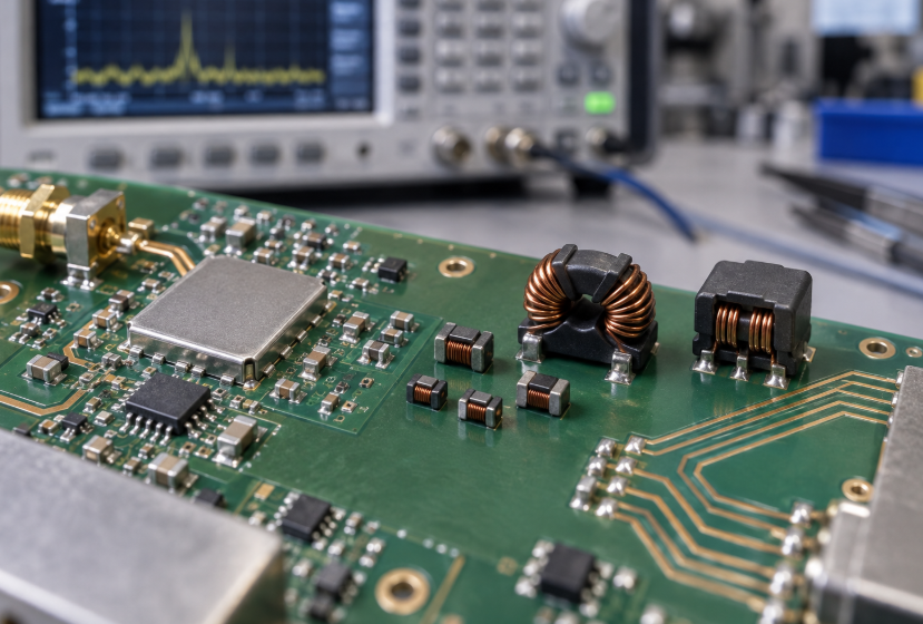
Inductor Comparison Table
| Inductor Type | Main Advantage | Main Limitation | Typical Application |
|---|---|---|---|
| Air core | Low core loss at high frequency | Low inductance for its size | RF circuits |
| Ferrite core | Strong high-frequency performance | Can lose inductance near saturation | Power conversion and EMI filters |
| Iron powder core | Good energy storage and soft saturation | Core loss may rise at higher frequencies | DC-DC converters and PFC circuits |
| Toroidal | Low magnetic leakage | More complex winding process | Power and audio filters |
| Wire-wound | Low DCR and strong current capacity | Usually larger than multilayer types | Power and RF circuits |
| Multilayer chip | Small, repeatable SMD package | Limited current and energy storage | Mobile and wireless devices |
| Thin-film | Tight tolerance and controlled RF behavior | Limited power handling | RF modules |
| Molded power | High current capacity and effective shielding | Larger volume than signal inductors | Power management |
| RF inductor | High Q and high SRF | Usually low current capacity | Wireless circuits |
| Coupled inductor/CMC | Energy coupling or common-mode suppression | Highly application-specific | Power converters and data lines |
How to Choose the Right Inductor for an Electronic Circuit
Inductance and Tolerance
Start with the inductance required by the circuit, but confirm the condition under which it is measured. Datasheets may specify inductance at a low test current and a particular frequency. In a working converter, DC bias and temperature can reduce that value.
Tolerance matters differently across applications. A power converter may accept a broad initial tolerance if full-load inductance remains within the design limit. An RF matching network can be far more sensitive to a small variation.
Rated Current and Saturation Current
Rated current is not a universal term. One manufacturer may base it on temperature rise, while another may emphasize saturation. Read the definitions and test conditions.
For a power design, compare peak current with Isat and RMS current with the thermal rating. Leave room for input variation, startup conditions, transient loads, ambient temperature, and component tolerance. Automotive designs also need the correct qualification level and temperature grade; the automotive electronics application area may involve wider thermal ranges and stricter documentation than standard consumer equipment.
DCR, Q Factor, and Self-Resonant Frequency
Low DCR reduces conduction loss in power circuits. It can improve efficiency, but choosing the lowest DCR part without considering core loss and package size may create a different thermal problem.
Q factor describes the relationship between stored and lost energy at a stated frequency. It is especially useful for RF filters and matching networks. Since Q changes with frequency, compare the curve rather than relying on one headline value.
Every real inductor contains parasitic capacitance. At its self-resonant frequency, the inductive and capacitive effects cancel. Above that point, the component can behave capacitively. RF designs should normally operate below the SRF with enough margin for tolerance and PCB parasitics.
Package Size, Shielding, and Operating Temperature
A smaller package saves board space but often increases DCR, thermal density, or magnetic-field concentration. Check whether the part can dissipate heat in the real PCB layout.
Shielding should be evaluated when the inductor sits near antennas, sensors, precision analog paths, or high-speed interfaces. For dense systems such as servers and processor boards, the interaction between power integrity, thermal limits, and PCB placement can be just as important as the nominal component value. DuoLink’s computing and semiconductor application overview provides related sourcing context for these assemblies.
Operating temperature is more than the ambient temperature printed on a project brief. The inductor’s self-heating must be added to local board temperature. Check whether the datasheet rating refers to ambient, component surface, or maximum internal temperature.
Datasheet and Procurement Checks Before Approval
Engineering approval and purchasing approval should use the same manufacturer part number and revision. Before placing an order, confirm the manufacturer, full MPN, inductance, tolerance, package dimensions, termination finish, packaging method, lifecycle status, qualification grade, and required compliance documents.
For alternative parts, compare curves and test conditions rather than matching only the visible BOM fields. Request the original datasheet and traceability information when the application has strict reliability requirements. If environmental compliance is part of the purchase specification, verify the declaration for the exact part number and production status instead of assuming that an entire series has identical documentation.
Conclusion
The top 10 types of inductors used in electronic circuits serve different electrical and mechanical needs. Air core and thin-film components favor controlled high-frequency behavior. Ferrite, iron powder, wire-wound, and molded constructions support power conversion across different current and frequency ranges. Toroidal designs reduce leakage, while coupled inductors and common-mode chokes manage energy transfer or unwanted noise between lines.
The best choice depends on working frequency, inductance under load, peak and RMS current, DCR, saturation behavior, Q factor, SRF, shielding, package size, and operating temperature. Start with the circuit requirements, then check the complete datasheet under realistic conditions.
If you are sourcing electronic components, Duolink Electronics is an independent distributor supplying integrated circuits, semiconductors, passive components, connectors, and other electronic parts. You can submit a part number or BOM for availability checks, package verification, alternative-part review, lead-time confirmation, and sourcing support.
Frequently Asked Questions
Can two inductors with the same inductance and package size be interchangeable?
Not automatically. Compare DCR, Isat, Irms, inductance under DC bias, SRF, Q, temperature rating, shielding, footprint tolerances, and qualification level. The manufacturer’s test conditions also need to match.
Should I select an inductor using saturation current or temperature-rise current?
Check both. Peak current must remain within the allowable saturation limit, while RMS current must stay within the thermal limit. The lower practical limit normally controls the design.
How much margin should an RF inductor have below its self-resonant frequency?
There is no fixed margin for every circuit. Review the impedance and Q curves across the complete operating band, including component tolerance and PCB parasitics. Avoid selecting a part whose SRF sits close to the highest required frequency.
What information should I include in an inductor RFQ?
Provide the full MPN, manufacturer, quantity, package, packaging format, target delivery date, and required compliance or traceability documents. If alternatives are acceptable, include the circuit function and the parameters that cannot change.
Can a shielded power inductor replace an unshielded model?
It may reduce magnetic leakage, but it is not a drop-in decision. Confirm footprint, height, DCR, thermal performance, saturation curve, inductance tolerance, and cost target before approval.
What should be checked when sourcing obsolete or hard-to-find inductors?
Confirm date code, packaging condition, storage history, moisture sensitivity where applicable, label consistency, traceability, and electrical test requirements. Any substitute should be reviewed by engineering before it enters production.

 English
  German
  Spanish
  French
  Chinese
  Italian