
A microcontroller can have a built-in CAN controller and still need another chip before it can communicate over a CAN cable. That chip is the CAN transceiver: the electrical interface between the controller and the network.
Understanding CAN transceiver basics helps engineers choose the right interface and purchasing teams avoid ordering a similar-looking part with the wrong supply, pin functions or data-rate capability. This guide explains how the device works, where it is used and what to verify before placing an order.
What Is a CAN Transceiver?
A CAN transceiver is an integrated circuit that connects a Controller Area Network controller to the physical bus. It converts the controller’s transmit signal into differential signals on CANH and CANL, then converts the bus state back into a receive signal for the controller.
In a typical node, the controller connects to the transceiver through TXD and RXD. CANH and CANL connect to the shared cable. The transceiver also needs power and ground; additional pins may control standby operation or provide a separate logic supply.
For buyers, the distinction matters: a conventional CAN transceiver provides the bus interface, while a CAN controller handles the communication protocol. Check which function the BOM requires before comparing components.
How Does a CAN Transceiver Work?
Sending and Receiving Through CANH and CANL
In normal operation, a low signal on TXD tells a typical high-speed CAN transceiver to drive a dominant bit, representing logic 0. CANH rises relative to CANL. A high TXD signal requests a recessive bit, representing logic 1, with little differential voltage between the wires when no other node drives dominant.
The receiver monitors the voltage difference between CANH and CANL and reports the bus state through RXD. This lets the controller observe the bus while transmitting as well as receiving. A dominant bus state overrides a recessive request, which supports CAN arbitration.
For a familiar 5 V high-speed CAN example, dominant levels are approximately 3.5 V on CANH and 1.5 V on CANL; recessive levels are often near 2.5 V on both. These are illustrative typical values, not universal acceptance limits. Use the specific device’s electrical specifications when evaluating measurements.
Why the Network Around the Chip Matters
A conventional high-speed CAN bus uses twisted-pair cabling and typically has 120 Ω termination at each physical end. Adding termination at every node changes the bus loading. Cable layout, branch lengths and termination affect signal quality, especially as data rates rise.
TI’s Introduction to the Controller Area Network explains these physical-layer fundamentals. For procurement, ask whether the engineer has approved the replacement in the actual network. A successful test on a short bench cable does not establish performance across the installed system.
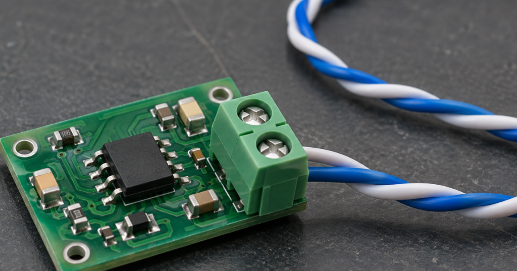
What Is the Difference Between a CAN Controller and a CAN Transceiver?
The controller builds and interprets CAN frames. The transceiver sends and receives their electrical representation. A controller may be integrated into a microcontroller or supplied as a separate chip. Use our microcontroller selection guide to check controller support, available pins, and the other interfaces required by the embedded system.
| Comparison | CAN controller | CAN transceiver |
|---|---|---|
| Main role | Implements the CAN protocol | Interfaces with the physical bus |
| Typical tasks | Frame handling, arbitration, error handling and message filtering | Differential driving and bus-state detection |
| Typical connections | Host interface or internal MCU connection; TX/RX interface | TXD/RXD, CANH/CANL, power and mode pins |
| Procurement check | Supported protocol and host integration | Electrical compatibility, timing and protection |
Some products integrate both functions. TI’s TCAN4550-Q1, for example, combines a CAN FD controller and transceiver. Integration must be confirmed from the manufacturer description rather than inferred from the word “CAN.”
DuoLink’s MCP2515-I/SO listing illustrates a stand-alone controller item. It should not be treated as a substitute for an external CAN transceiver. When reviewing a module, inspect its schematic or component list to establish which functions are included.
What Are the Main Types of CAN Transceivers?
High-speed operation, CAN FD support and isolation describe different attributes. An isolated transceiver can also support high-speed CAN and CAN FD.
High-Speed CAN Transceivers
High-speed CAN transceivers provide the differential interface commonly used for Classical CAN networks, with Classical CAN operating at rates up to 1 Mbit/s. Match the required physical-layer characteristics, operating modes and timing to the system specification.
Legacy low-speed fault-tolerant CAN interfaces are another category. Do not assume that a high-speed part is a suitable replacement simply because both devices have CANH and CANL pins.
CAN FD Transceivers
CAN FD permits a faster data phase than the arbitration phase when configured accordingly. The transceiver must support the intended timing and data-phase rate; the controller must also support CAN FD. Replacing only the transceiver cannot add CAN FD protocol support to a Classical CAN controller.
There is no single maximum speed for all CAN FD transceivers. TI’s TCAN1042 family includes 2 Mbit/s versions and “G” variants specified for up to 5 Mbit/s. Other devices have different limits. Record the arbitration rate and data-phase rate separately in the engineering requirements.
Isolated CAN Transceivers
An isolated CAN transceiver provides a galvanic isolation barrier between the logic side and the bus side. It can help address ground-potential differences and isolation requirements in industrial or power systems.
Signal isolation does not automatically include isolated power. Check how each side is supplied, along with the required working voltage, isolation classification, package spacing and system layout. The TI ISO1042 datasheet is a useful example of an isolated CAN FD device with separate logic-side and bus-side supplies.
Where Are CAN Transceivers Used?
CAN transceivers appear in automotive control networks, industrial equipment and other systems that exchange control or status information over CAN.
In vehicles, they connect electronic control units used in body electronics and other CAN-connected subsystems. For automotive purchasing, confirm the exact orderable device’s qualification, temperature grade and customer approval. A CAN-compatible industrial device is not automatically approved for a vehicle project.
Industrial applications include motor drives, distributed I/O and machine controllers. Ground differences, connectors exposed to transients and cable routing can influence the choice of interface and protection. Ask engineering to define those conditions before requesting an alternative.
Battery systems, diagnostic tools and embedded equipment may also use CAN interfaces. The application name alone does not establish whether isolation, CAN FD or a particular qualification is required. DuoLink’s automotive electronics page provides sourcing context; the approved design remains the basis for selecting a part.
How Do You Choose the Right CAN Transceiver?
Start with the schematic and network requirements. Supply voltage, speed and package size are useful filters, but the final comparison must include pin functions and operating behavior.
| Selection factor | What to verify | Reason for checking |
|---|---|---|
| Supply and logic levels | VCC range, VIO if present, TXD thresholds and RXD output levels | A 3.3 V MCU does not establish the transceiver’s required supply |
| Protocol and timing | Classical CAN/CAN FD support, data-phase rate and worst-case delays | A headline speed alone does not establish network timing margin |
| Package and pinout | Package drawing, footprint, exposed pad and every pin function | Similar 8-pin devices may have different connections |
| Protection | Bus-fault limits, ESD test conditions, undervoltage response and dominant timeout | Protection claims need to match the expected fault conditions |
| Temperature | Recommended operating range and temperature definition | Ambient and junction ratings describe different limits |
| Power modes | Standby, wake-up behavior and unpowered bus loading | Replacement behavior can affect sleeping or disconnected nodes |
| Isolation | Working voltage, barrier specifications, spacing and power arrangement | The complete isolation design needs review |
Supply and logic compatibility deserve separate attention. Some devices use a 5 V bus-side supply and a VIO input for lower-voltage logic. Other devices operate from 3.3 V. TI’s TCAN3413 is an example of a 3.3 V CAN FD transceiver with flexible logic interfacing; this does not make it interchangeable with every 5 V part.TI.com
For a replacement, create a comparison against the original datasheet and have engineering approve the differences. Pin 5 or pin 8 may serve different purposes across families. A package match is only one part of the review.
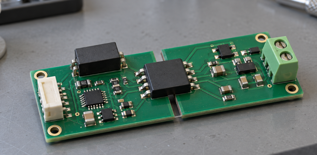
What Should Buyers Check Before Ordering CAN Transceivers?
Confirm the Complete Manufacturer Part Number
Keep every letter, number and ordering suffix in the RFQ and purchase order. A shortened family name can hide differences in speed, logic supply, protection, package or packing format.
The TCAN1042 family datasheet provides a concrete example: “G” identifies faster variants, “V” identifies versions with a separate I/O supply, and “H” identifies a different bus-fault protection rating. These meanings are specific to this family; do not apply them to other manufacturers.
Separate Availability From a Catalog Listing
Ask whether the quoted material is physically held, supplier-held or still being sourced. Request a dated quantity confirmation, dispatch estimate, packaging condition and disclosure of any split delivery. A product page is a starting point for an inquiry, not proof of current stock.
If an alternative is offered, keep it separate from the requested line item until engineering approves it. Record the approved complete part number rather than accepting “equivalent CAN chip” on the quotation.
Agree on Evidence and Receiving Checks
Define the required source documentation, date-code restrictions and lot requirements before ordering. Request available label and packaging photos and ask whether the material has been repacked. Photos help identify discrepancies but cannot by themselves establish authenticity or an uninterrupted chain of custody.
At receiving, compare the shipment with the purchase order and agreed documents. Check quantity, package condition, labels and visible component condition. Where risk justifies testing, agree on the test scope and acceptance criteria in advance; neither visual inspection nor a limited functional check proves every datasheet parameter.
Hold material for clarification when the part number, package or agreed documentation does not match. Resolving a discrepancy before production is more useful than relying on a general supplier assurance afterward.
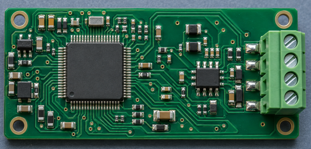
Conclusion
Understanding CAN transceiver basics starts with the division of work: the controller manages CAN communication, and the transceiver connects it electrically to the bus. Selecting the right part requires matching that interface to the supply rails, network timing, package, protection and application requirements.
DuoLink Electronics is an independent electronic-component supplier offering BOM quotation and sourcing support. To request a CAN transceiver quotation, send the complete manufacturer part number, quantity, target application, required delivery date and documentation requirements. Identify any proposed alternative separately so its suitability can be reviewed before purchase.duolinkelectronics.com
Frequently Asked Questions
Does a microcontroller with a CAN controller still need a transceiver?
Usually, yes. An integrated CAN controller commonly provides logic-level transmit and receive signals. An external transceiver supplies the bus interface unless the device already integrates that function.
Will a CAN FD transceiver upgrade a Classical CAN controller?
No. The controller must support CAN FD frames. The transceiver, network timing and configuration must also support the intended operating rates.
Is every CAN FD transceiver rated for 5 Mbit/s?
No. Ratings vary by device and sometimes by suffix within a family. Verify the exact variant and the conditions attached to its specified rate.
Does an isolated CAN transceiver include isolated power?
Not necessarily. Review the power architecture. A device may isolate the signal path while requiring a separate isolated supply for the bus side.


 English
 German
 Spanish
 French
 Chinese
 Italian