
A NOR Flash replacement can fit the PCB and still fail to boot. Capacity and pin count are only the first checks: the processor also needs the right read commands, reset behavior, protection settings, and address handling.
This guide to the Top 10 NOR Flash ICs Used in Embedded Systems compares ten serial NOR devices for firmware, boot code, and related storage. The order follows the selected shortlist rather than a verified popularity ranking. Application suggestions below are engineering starting points, not evidence that a device is qualified for a particular end product.
Start with the firmware memory map. A 64 Mb device holds 8 MiB, a 128 Mb device holds 16 MiB, and a 256 Mb device holds 32 MiB. That is raw capacity before reserving space for the bootloader, recovery image, configuration data, and future growth.
| NOR Flash IC | Density / raw capacity | Interface overview | Main selection check |
|---|---|---|---|
| Winbond W25Q128JV | 128 Mb / 16 MiB | Single, Dual, Quad SPI | Exact package suffix and Quad-mode setup |
| GigaDevice GD25Q64E | 64 Mb / 8 MiB | Single, Dual, Quad SPI | Firmware/update capacity and footprint |
| Macronix MX25L12835F | 128 Mb / 16 MiB | Single, Dual, Quad SPI; QPI | Host support for the selected protocol |
| Infineon S25FL128S | 128 Mb / 16 MiB | SPI with multi-I/O, including Quad reads | Hybrid or uniform erase architecture |
| Micron MT25QL128ABA | 128 Mb / 16 MiB | Multiple-I/O serial NOR | Full ordering code and driver configuration |
| ISSI IS25LP128F | 128 Mb / 16 MiB | Multi-I/O SPI, QPI, DTR | Read timing and controller capability |
| Microchip SST26VF064B | 64 Mb / 8 MiB | SPI and Serial Quad I/O (SQI) | Protection setup and voltage/speed limits |
| Renesas AT25SF128A | 128 Mb / 16 MiB | Single, Dual, Quad SPI | Boot/read mode and package selection |
| Infineon S25FL256S | 256 Mb / 32 MiB | SPI with multi-I/O, including Quad reads | Addressing above 16 MiB and erase layout |
| ISSI IS25LP064A | 64 Mb / 8 MiB | Multi-I/O SPI, QPI, DTR | Voltage-dependent read timing |
These are family-level comparisons. Package, temperature grade, timing limits, and available options must be confirmed against the complete manufacturer ordering code.
Winbond W25Q128JV
The W25Q128JV is a 128 Mb serial NOR device operating from 2.7 V to 3.6 V, with Single, Dual, and Quad SPI support. It is a candidate for a 3.3 V embedded board that needs 16 MiB of external nonvolatile storage. Its suitability still depends on the host’s boot interface and the chosen read operation.
Put the orderable part number on the purchase order, including its suffix. DuoLink’s W25Q128JVSIQ product page identifies a specific variant; the shorter W25Q128JV name does not specify every package and grade detail.
Before approving another vendor’s 128 Mb flash as a substitute, check the Quad Enable procedure, status-register writes, and reset path. Preserve protection bits when configuring the interface. A successful JEDEC ID read confirms basic communication, but it does not validate full-speed reads, firmware updates, or authenticity.
GigaDevice GD25Q64E
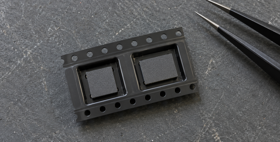
GigaDevice lists the GD25Q64E as a 64 Mb, 2.7 to 3.6 V device with Single, Dual, and Quad I/O and a headline frequency of 133 MHz. Its official product page lists several package options, including different SOP-8 widths and leadless formats. Those options require different footprint checks.
The first decision is whether 8 MiB is enough. Consider an illustrative update plan with two 3 MiB firmware slots. Together they consume 6 MiB, leaving 2 MiB for the bootloader, metadata, configuration, and growth. That allocation may work, but the actual linked images and erase-aligned partitions must fit.
When requesting a quotation, include the complete package and temperature suffix. For an alternate-source evaluation, compare register behavior and the host’s supported device table as well as voltage and density. Do not approve a substitution based on an “8-pin SPI flash” description.
Macronix MX25L12835F
The MX25L12835F provides 128 Mb of storage with a 2.7 to 3.6 V supply. Macronix lists Single, Dual, and Quad I/O operation, QPI support, and speeds up to 133 MHz. QPI uses four lines for the instruction phase as well as other transfer phases; that differs from Quad SPI operations that send the instruction on one line.
This distinction matters when the boot ROM supports fewer protocols than the application driver. The firmware may enable a faster operating mode after boot, but the device must return to a state the boot ROM understands after reset.
Ask engineering to validate the entire startup sequence with the selected ordering code. Include cold power-up, watchdog reset, and recovery after an interrupted update. For procurement, record the approved part and package drawing in the BOM so a later quotation does not silently introduce another Macronix device with a similar name.
Infineon S25FL128S
The S25FL128S is a 128 Mb member of Infineon’s FL-S serial NOR family. Its erase architecture deserves particular attention: the family includes hybrid layouts with a limited region of small sectors and uniform layouts using larger sectors. Small-sector erase is not available at every address on every variant.
A settings partition designed around 4 KiB erases therefore needs an address-by-address check. If the proposed part places that partition in a larger erase region, changing one setting may require preserving and rewriting neighboring data. Infineon’s FL-S datasheet is the relevant reference for those layout options.
DuoLinks S25FL128SAGMFI001 listing can serve as a starting point for an inquiry. Confirm the complete ordering code and sector layout with engineering before accepting a quotation. Another FL-S suffix should receive a separate compatibility review.
Micron MT25QL128ABA
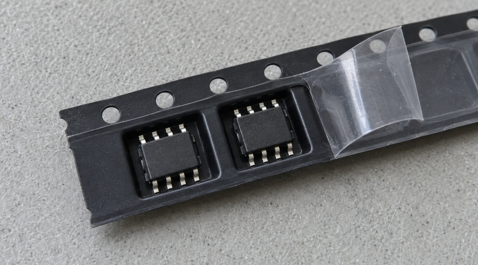
Micron describes the MT25QL128ABA as a 128 Mb, 3 V, multiple-I/O SPI flash device. The full ordering code adds information that the base name omits. For example, Micron’s page for MT25QL128ABA1EW9-0SIT identifies a particular WPDFN package and an operating range of −40°C to +85°C.
Use that level of specificity in an RFQ. A quotation for the base family alone leaves room for a package or grade mismatch, even when the density looks correct.
For an existing board, check the bootloader’s device support and register configuration against the exact variant. A generic SPI NOR driver may handle the basic read and program commands while still needing device-specific initialization. Keep the approved driver version, memory map, and full MPN together in the qualification record; this makes later source changes easier to assess.
ISSI IS25LP128F
The IS25LP128F offers 128 Mb of storage and supports multi-I/O SPI, QPI, and double transfer rate (DTR) operation. ISSI’s documentation lists fast-read operation up to 166 MHz. The “LP” device belongs to a different voltage option from the similarly named “WP” device, so the prefix must remain part of the purchasing check.
The controller and PCB must support the chosen command and timing before the higher clock becomes useful. DTR also requires host support for transfers on both clock edges. Buying a faster flash does not automatically shorten startup time.
For qualification, measure the operation that matters: boot-image loading, mapped-code reads, or asset transfers. Test at the intended voltage and temperature limits with the actual dummy-cycle configuration. Purchasing should retain the approved full ordering code rather than accepting any 128 Mb ISSI flash as equivalent.
Microchip SST26VF064B
The SST26VF064B is a 64 Mb device with SPI and Serial Quad I/O support. Its operating frequency depends on supply voltage: the datasheet specifies up to 104 MHz over 2.7 to 3.6 V and up to 80 MHz over the wider 2.3 to 3.6 V range. A board that can drop below 2.7 V needs the corresponding timing review.
Protection behavior is another reason to check the exact device. The SST26VF064B/SST26VF064BA datasheet covers related variants, but a shared document does not make their configuration interchangeable.
Before production approval, verify the programming tool’s initialization and protection sequence using the ordered part. Program an image, read it back, and confirm the intended write-protected regions. These functional checks support qualification; they do not establish the source history of an incoming lot.
Renesas AT25SF128A
The AT25SF128A is a 128 Mb device operating from 2.7 V to 3.6 V. Renesas lists Single, Dual, and Quad SPI interfaces, along with continuous-read, wrap, and burst features for execute-in-place (XIP) use. XIP means the processor fetches code directly from external flash through a suitable memory interface.
Check whether the host can use those features throughout startup and code execution. A controller’s support for Quad SPI does not prove support for every continuous-read or burst configuration.
Check the Renesas AT25SF128A product and current ordering information when selecting the package and grade. For a replacement evaluation, verify the boot ROM requirements first, then the application driver’s read mode and reset handling. Keep this work separate from a purchasing comparison of lead time and documentation.
Infineon S25FL256S
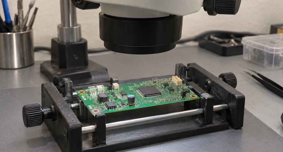
The S25FL256S increases raw capacity to 256 Mb, or 32 MiB. That can provide room for larger firmware images or recovery partitions, but it crosses a boundary that a 128 Mb device does not: a three-byte byte address covers only 16 MiB.
Engineering must confirm how the host reaches the upper half of the array, including its use of extended addressing or four-byte commands. Qualification should read and program locations on both sides of that boundary, then repeat the boot test after reset.
Erase layout remains part of the selection. Confirm the ordered architecture and align partitions accordingly. Treat a move from S25FL128S to S25FL256S as a memory-system change requiring approval, even if the proposed package fits the board. More capacity alone does not establish that the boot ROM, flash driver, and manufacturing programmer can use it correctly.
ISSI IS25LP064A
The IS25LP064A is a 64 Mb serial NOR device supporting multi-I/O SPI, QPI, and DTR. ISSI specifies a 2.3 to 3.6 V supply, with fast reads up to 133 MHz at 2.7 to 3.6 V and up to 104 MHz over 2.3 to 3.6 V. Its voltage and frequency conditions should be evaluated together.
It is a candidate for an 8 MiB design whose host supports the required commands. Before replacing a larger flash, check the actual occupied address range as well as total image size. A small image stored near the top of a 16 MiB map still needs relocation when moving to an 8 MiB part.
Approve samples with the intended bootloader and programmer before buying a production lot. Confirm that reset returns the system to a usable protocol state and that protection settings survive the intended update sequence.
The following checks apply when sourcing any of these ten devices:
| Purchase checkpoint | Evidence or action | When to pause approval |
|---|---|---|
| Exact part identity | Full MPN, package drawing, grade, current datasheet | Quote omits a suffix or introduces an unapproved variant |
| System compatibility | Host documentation and board validation covering boot, erase, program, reset, and address range | Proposed alternate has only a density/pin-count comparison |
| Lot and packaging | Agreed date-code/lot limits, packaging condition, current photos, and available source records | Material differs from the agreed requirements or cannot be clarified |
| Compliance and qualification | Exact-part declarations and application-required qualification records | Family-level claims replace evidence for the ordered device |
| Incoming acceptance | Agreed inspection scope, sampling plan, criteria, and escalation process | Markings, dimensions, records, or electrical behavior conflict |
Visual inspection can identify discrepancies, but appearance alone cannot prove authenticity. Read-ID and functional tests also have limits; choose the evidence and test scope according to the application and sourcing risk. For boards that update in the field, include controlled power-interruption tests and verify recovery to a known-good image. Define the test conditions and acceptance criteria with engineering before production
approval.
Fazit
The Top 10 NOR Flash ICs Used in Embedded Systems span 8 MiB, 16 MiB, and 32 MiB options. The right choice is the one that fits the firmware plan, boots reliably with the host, supports the update process, and can be purchased under a complete, approved ordering code.
DuoLink Electronics is an independent electronic-component supplier offering sourcing inquiries and BOM support. To request a quotation, send the full part number, manufacturer, quantity, package, temperature grade, and any date-code or documentation requirements. Identify whether you need the exact device or can consider engineering-approved alternatives, so the inquiry starts with clear acceptance requirements.
Häufig gestellte Fragen
Which of these NOR Flash ICs is best for firmware storage?
There is no single best device across all hosts. Start with capacity and boot-ROM support, then compare voltage, read timing, erase layout, update recovery, and the available ordering options.
Is a 128 Mb NOR Flash the same as 128 MB?
No. A 128 Mb flash contains 16 MiB of raw storage. Bits and bytes differ by a factor of eight. Usable firmware space is smaller after reserving other partitions.
Can I replace one brand of Quad SPI NOR Flash with another?
Only after compatibility validation. Compare the full MPN, pinout, voltage, commands, registers, reset behavior, protection, erase layout, and timing. Matching density and package are insufficient.
Why does a 256 Mb flash need extra addressing checks?
Its 32 MiB array exceeds the 16 MiB range of three-byte byte addressing. The boot ROM, driver, and production programmer must support the device’s method of accessing higher addresses.


 German
 English
 Spanish
 French
 Chinese
 Italian