
What is a capacitor, and why does almost every electronic circuit need one?
A capacitor is a passive electronic component that stores electrical energy in an electric field. That description is technically correct, but it only explains a small part of what a capacitor actually does in a circuit.
In real electronic designs, capacitors stabilize power rails, remove electrical noise, smooth rectified voltage, separate AC signals from DC bias, create timing delays, and support fast current demand near integrated circuits. One PCB may contain dozens or even hundreds of capacitors, each doing a slightly different job.
The difficult part is rarely finding a capacitor with the right capacitance printed on the datasheet. The real challenge is deciding whether that capacitance will still be available under the actual working voltage, temperature, frequency, ripple current, and physical package conditions.
From the sourcing side, this is also where many substitution problems begin. Two capacitors marked “10 µF, 25 V” may look interchangeable on a BOM, yet their ESR, dielectric, DC bias behavior, package construction, lifetime, polarity, and frequency response can be very different.
This guide explains how capacitors work, the main capacitor types, the specifications that matter, and what you should check before selecting or sourcing one. Our overview of common electronic components on a PCB places capacitors alongside the other component families and their purchasing checks.
1. What Is a Capacitor?
A capacitor is an electronic component designed to hold electric charge temporarily.
Its basic electrical relationship is:
C = Q / V
where:
- C is capacitance in farads
- Q is electric charge
- V is voltage across the capacitor
A larger capacitance means the component can store more charge at a given voltage.
Most electronic capacitors are rated in microfarads (µF), nanofarads (nF), or picofarads (pF). A large electrolytic capacitor in a power supply may be hundreds or thousands of microfarads, while a small capacitor in a high-frequency RF circuit may be only a few picofarads.
Capacitance alone does not tell you how a capacitor will perform. The dielectric, construction, voltage rating, ESR, temperature range, frequency behavior, and package all matter.
Basic Structure of a Capacitor
At its simplest, a capacitor contains two conductive electrodes separated by an insulating material called the dielectric.
The dielectric prevents normal DC conduction between the electrodes. When voltage is applied, charge builds on the two sides and an electric field forms across the dielectric.
The basic physical relationship can be described as:
C = εA / d
where A is electrode area, d is the distance between electrodes, and ε represents the permittivity of the dielectric.
This explains why capacitor technology varies so much. Manufacturers can increase capacitance by using larger effective electrode areas, thinner dielectric layers, or dielectric materials with higher permittivity.
An MLCC, for example, contains many alternating ceramic and metal layers inside a very small package. An aluminum electrolytic capacitor uses a completely different internal structure to obtain much larger capacitance values.
TDK describes the same core structure: two electrodes separated by a dielectric, with the dielectric helping increase the amount of charge that can be stored.
Capacitor vs. Battery: What Is the Difference?
A capacitor and a battery can both store energy, but they should not be treated as the same device.
| Feature | Capacitor | Battery |
|---|---|---|
| Energy storage | Electric field | Chemical energy |
| Charge/discharge speed | Usually very fast | Usually slower |
| Energy capacity | Relatively low | Much higher |
| Typical circuit role | Filtering, buffering, timing, coupling | Long-term power source |
| Cycle capability | Very high for many capacitor types | Limited by battery chemistry |
A capacitor can respond to fast changes in current much more quickly than a conventional battery. That makes it useful beside processors, regulators, switching devices, and other loads that change current rapidly.
The energy stored in an ideal capacitor is:
E = ½CV²
Notice that voltage is squared. A change in operating voltage can have a large effect on stored energy.
2. How Does a Capacitor Work?
A capacitor works by building an electric field between its electrodes.
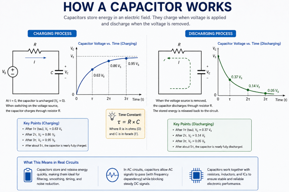
When a voltage source is connected, electrons accumulate on one electrode while charge is removed from the other. The voltage across the capacitor rises as the electric field develops.
Once the capacitor voltage reaches the applied DC voltage in an ideal steady-state circuit, charging current falls to zero.
Real capacitors are not ideal components. They have leakage current, equivalent series resistance, equivalent series inductance, dielectric losses, and other parasitic characteristics. These details become increasingly important in power electronics and high-frequency designs.
How a Capacitor Charges and Discharges
When an uncharged capacitor is first connected to a DC source through a resistor, current is initially high. As the capacitor charges, its voltage rises and charging current decreases.
For a basic RC circuit, the time behavior is controlled by the time constant:
τ = RC
After one time constant, the capacitor has charged to about 63% of its final voltage. After several time constants, it approaches the supply voltage.
During discharge, the process moves in the opposite direction. Stored energy is released into the circuit and capacitor voltage falls.
This ability to absorb and release energy quickly is what lets capacitors handle short voltage disturbances, supply brief current pulses, and create predictable delays in timing circuits.
How Capacitors Behave in AC and DC Circuits
You may often hear that a capacitor “blocks DC and passes AC.” It is a useful starting point, but it needs some context.
With steady DC, a capacitor charges and eventually stops drawing significant current apart from real-world leakage. During a change in DC voltage, current still flows while the capacitor charges or discharges.
With AC, voltage keeps changing direction. The capacitor repeatedly charges and discharges, so an alternating current relationship appears in the circuit.
TDK explains this behavior through displacement current and notes that the ease with which AC passes depends on both capacitance and frequency.
Capacitive reactance is:
Xc = 1 / (2πfC)
As frequency increases, reactance falls. Increasing capacitance also lowers reactance.
This is why a 100 nF ceramic capacitor placed close to an IC may suppress high-frequency noise better than a physically larger electrolytic capacitor, even though the electrolytic has much higher nominal capacitance.
At very high frequencies, parasitic inductance also matters. Once a capacitor passes its self-resonant frequency, its behavior can become increasingly inductive. This is one reason decoupling networks often use more than one capacitor value and package size.
3. What Are the Main Functions of a Capacitor?
Capacitors perform several electrical jobs depending on where they are placed in a circuit.
Energy Storage and Power Stabilization
A capacitor can supply energy for short periods when a circuit suddenly demands current.
This is common around processors, memory devices, power-management ICs, motor drivers, and switching circuits. The capacitor acts as a local energy reservoir, helping keep the supply voltage within an acceptable range while the power source or regulator responds.
Large bulk capacitors handle slower and larger energy changes. Smaller ceramic capacitors are normally used closer to semiconductor power pins to handle faster transients.
If you want to understand why those local capacitors matter around semiconductor devices, our guide to integrated circuits and their functions gives more background on how ICs interact with surrounding passive components.
Filtering, Smoothing, and Noise Reduction
Capacitors are widely used to remove unwanted AC components from a voltage or signal.
After AC is rectified in a power supply, the output is not perfectly smooth DC. A reservoir capacitor charges near voltage peaks and releases energy between them, reducing ripple.
In switching power supplies, capacitor selection becomes more demanding. Ripple current, ESR, switching frequency, capacitance, and thermal performance all affect the result.
Low ESR is often desirable because current flowing through ESR generates heat:
P ≈ I² × ESR
A capacitor with sufficient capacitance but poor ripple-current capability may still be unsuitable.
Coupling, Decoupling, and Timing Functions
A coupling capacitor transfers an AC signal between circuit stages while blocking unwanted DC bias.
A decoupling or bypass capacitor provides a low-impedance path for unwanted AC noise around a power rail.
A capacitor can also work with a resistor to establish a delay or frequency-dependent response. RC networks are used in timing, filtering, reset circuits, oscillator networks, and signal shaping.
The same component category can perform very different jobs. That is why selecting a capacitor only by capacitance and voltage rating often misses the actual design requirement.
4. What Are the Different Types of Capacitors?
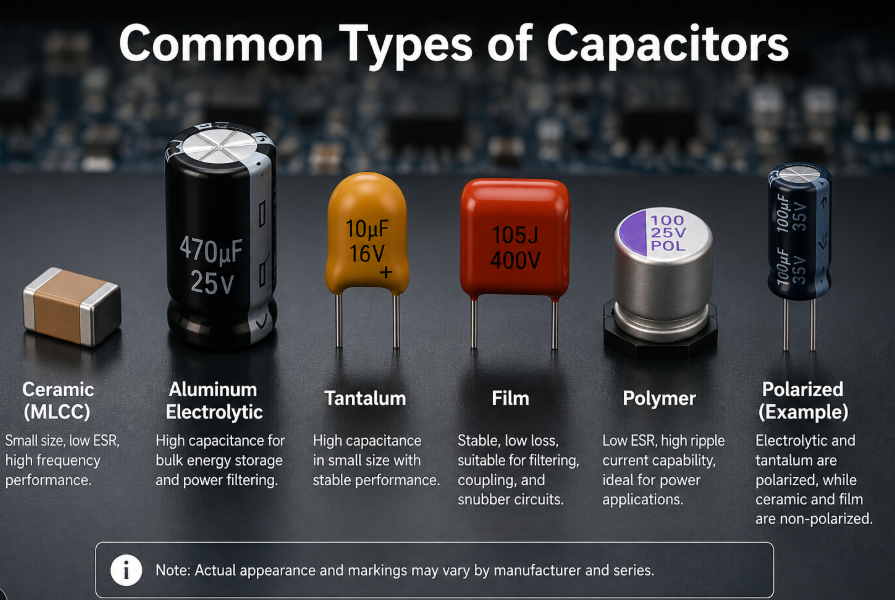
There is no single capacitor technology that is best for every circuit. Each construction trades capacitance density, ESR, voltage handling, stability, frequency response, size, lifetime, and cost differently.
You can also review available capacitor categories and part numbers when comparing different constructions and specifications.
Ceramic Capacitors and MLCCs
Ceramic capacitors, especially multilayer ceramic capacitors or MLCCs, are among the most widely used capacitors on modern PCBs.
They are compact, available in very small SMD packages, have low parasitic inductance, and perform well at high frequencies.
Common dielectric classes include C0G/NP0, X7R, and X5R.
C0G capacitors offer very good capacitance stability and low losses, making them useful in precision and high-frequency circuits. X7R and X5R parts provide much higher capacitance density, which makes them common for power decoupling and general-purpose filtering.
There is one important issue that purchasing teams sometimes miss: nominal capacitance is not always effective capacitance.
High-dielectric-constant MLCCs such as many X5R and X7R parts can lose capacitance when DC voltage is applied. Murata notes that DC bias can reduce effective capacitance in these ceramic dielectrics, while C0G-type temperature-compensating capacitors do not show the same behavior.
This means a 10 µF MLCC on the datasheet may provide noticeably less than 10 µF in the real circuit.
Package size can also affect this behavior. When replacing an MLCC with a smaller package, do not assume identical capacitance, voltage, and dielectric markings guarantee identical effective performance.
Aluminum Electrolytic Capacitors
Aluminum electrolytic capacitors provide high capacitance at practical sizes and are widely used for bulk energy storage, DC-link support, power-supply smoothing, and low-frequency filtering.
Most are polarized.
Compared with ceramic capacitors, conventional aluminum electrolytics normally have higher ESR and greater leakage. Their useful life is also affected by temperature, ripple current, and operating conditions.
This makes lifetime data important in equipment expected to operate for many years.
For power applications, I normally check more than capacitance and voltage. Ripple-current rating, ESR or impedance, rated temperature, endurance data, dimensions, lead spacing, and mounting style all deserve attention.
Tantalum Capacitors
Tantalum capacitors offer relatively high capacitance in a small package and can provide stable electrical characteristics.
Most traditional tantalum capacitors are polarized, so orientation matters.
Voltage stress also deserves careful review. A replacement should not be selected merely because its rated voltage is slightly above the circuit voltage. Manufacturer derating recommendations and application conditions need to be checked.
Tantalum parts remain useful where compact size, capacitance stability, and predictable performance are valued, but they should be treated as a distinct capacitor technology rather than a direct substitute for any ceramic or electrolytic capacitor.
Film Capacitors
Film capacitors use plastic film as the dielectric.
They are known for stable capacitance, low dielectric losses, low leakage, and strong pulse-handling characteristics. They are common in filtering, coupling, snubber circuits, motor applications, power electronics, and circuits where capacitance stability matters.
Their trade-off is usually physical size. For the same capacitance, a film capacitor may occupy considerably more board or enclosure space than an MLCC or electrolytic part.
Polymer Capacitors
Polymer capacitors replace the liquid electrolyte used in traditional electrolytic designs with a conductive polymer system.
A major advantage is low ESR.
This makes polymer capacitors attractive for power rails carrying high ripple currents or supplying fast-changing digital loads. They are found around processors, FPGA power rails, computing hardware, communications equipment, and DC-DC converters.
They still have application limits. Rated voltage, leakage current, surge conditions, operating temperature, and manufacturer guidance need to be checked before replacing another capacitor technology.
Polarized vs. Non-Polarized Capacitors
Polarity is an easy specification to overlook during BOM substitution, yet an incorrect replacement can cause immediate reliability problems.
Ceramic and many film capacitors are non-polarized.
Aluminum electrolytic, tantalum, and many polymer capacitors are polarized.
| Capacitor Type | Typical Strength | Main Point to Check |
|---|---|---|
| Ceramic / MLCC | Small size, high-frequency performance | DC bias, dielectric, cracking risk |
| Aluminum electrolytic | High bulk capacitance | Polarity, ESR, ripple current, lifetime |
| Tantalum | High capacitance density | Polarity, voltage derating |
| Film | Stability, low loss, pulse capability | Physical size |
| Polymer | Low ESR, strong ripple performance | Voltage, leakage, application limits |
Never infer polarity only from capacitance value or package appearance. Use the manufacturer datasheet and part marking.
5. Key Capacitor Specifications You Should Know
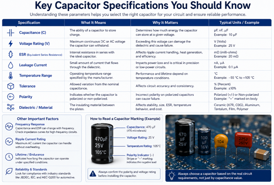
Capacitance is only the first line of a capacitor specification.
When we review a capacitor for sourcing or substitution, I normally look at the electrical and mechanical parameters together.
Capacitance and Capacitance Tolerance
Capacitance describes the nominal value, while tolerance defines how far the manufactured value may vary around it.
A 10 µF capacitor with ±20% tolerance may fall within a relatively broad initial range.
That still does not represent every operating condition. Temperature, frequency, aging, and DC bias can move the effective value further.
For MLCCs, this distinction is especially important. The number printed in a catalog should not automatically be treated as the capacitance available in the finished circuit.
Voltage Rating and Working Voltage
The voltage rating is the maximum value defined by the manufacturer under specified conditions. It should not automatically become the target continuous operating voltage.
Design margin may be required depending on capacitor technology, temperature, transients, reliability target, and manufacturer recommendations.
A higher voltage rating can sometimes replace a lower-rated capacitor, but electrical performance and physical compatibility still need checking.
ESR, Leakage Current, and Temperature Rating
ESR, or equivalent series resistance, affects power loss, ripple performance, filtering behavior, and heating.
Leakage current represents the small current that continues to flow through a real capacitor even after it has charged.
Temperature rating defines the approved operating range, but temperature also influences actual lifetime and electrical performance.
This becomes especially important for electrolytic capacitors placed close to hot components such as MOSFETs, transformers, power resistors, or heat sinks.
Dielectric Material, Package Size, and Polarity
For ceramic capacitors, dielectric code may matter as much as capacitance.
For electrolytic capacitors, case diameter, height, lead spacing, mounting method, and polarity can prevent an otherwise suitable electrical replacement from fitting the PCB.
When checking a BOM, I use a comparison closer to this:
| Parameter | Why It Matters |
|---|---|
| Capacitance | Determines charge storage and circuit response |
| Rated voltage | Sets voltage capability |
| Effective capacitance | Shows real capacitance under operating conditions |
| Tolerance | Defines initial allowed variation |
| ESR / impedance | Affects ripple, heat, filtering, transient response |
| Ripple-current rating | Important in power circuits |
| Temperature range | Affects suitability and lifetime |
| Dielectric | Affects stability and DC bias |
| Package / dimensions | Determines PCB compatibility |
| Polarity | Prevents incorrect installation or substitution |
That table is much closer to how a real substitution should be reviewed.
6. Common Capacitor Applications and How to Choose the Right Type
The best way to choose a capacitor is to start with the circuit function, not the capacitor family.
Ask what the capacitor must actually do.
Capacitors in Power Supplies and Voltage Regulation
Power circuits may need several capacitor types at once.
A bulk electrolytic capacitor can handle lower-frequency energy storage. A polymer capacitor may provide lower ESR near a regulator output. Small MLCCs can suppress high-frequency noise near semiconductor pins.
Look at:
- input and output voltage
- ripple-current level
- switching frequency
- required effective capacitance
- ESR
- ambient and internal temperature
- transient voltage
- expected operating life
For automotive designs, these requirements can become even stricter because vibration, temperature cycling, transients, and long service life all affect component selection. Our automotive electronics applications page gives more context on the types of electronic systems used in this environment.
Capacitors in Filtering, Signal, and Timing Circuits
Signal circuits usually care about more than bulk capacitance.
A timing capacitor may require good capacitance stability. A precision filter may need a dielectric with low temperature drift. An RF circuit may depend on Q factor, parasitic inductance, and self-resonant frequency.
For coupling applications, the capacitance must be large enough that reactance is low at the lowest required signal frequency.
This is the part where choosing “the same capacitance” can still produce a different circuit result.
Choosing a Capacitor Based on Capacitance, Voltage, ESR, and Application
Start with four questions:
What capacitance is needed under real operating conditions?
Do not rely only on nominal value, especially with high-capacitance MLCCs.
What voltage will the capacitor actually see?
Include normal DC voltage, ripple, switching peaks, startup conditions, and possible transients.
How much current will flow through it?
High ripple current combined with ESR produces heat.
What behavior does the circuit need?
A bulk storage capacitor, RF capacitor, precision timing capacitor, snubber capacitor, and decoupling capacitor should not be selected using the same logic.
This is the core of capacitor selection. Start from the electrical job, then narrow down the technology.
What to Check When Sourcing Capacitors for a BOM
From the procurement side, this section is often more important than the basic definition of a capacitor.
When I receive a capacitor line in a BOM, I prefer the original manufacturer part number rather than a description such as:
10 µF / 25 V / 0805 capacitor
That description leaves too many questions unanswered.
Before approving supply or an alternative, check the manufacturer, complete MPN, capacitance, rated voltage, dielectric, tolerance, package, temperature range, polarity, ESR or impedance where relevant, ripple-current rating where relevant, and mounting configuration.
For production purchasing, I would also review:
- lifecycle status
- authorized or traceable supply information
- date and lot information where required
- manufacturer datasheet revision
- packaging method and quantity
- environmental documentation requested by the customer
- dimensional compatibility
- qualification requirements for the end application
For products entering regulated markets, compliance documentation should be checked against the actual application and current rules. The European Commission maintains the official RoHS Directive information, including implementation and exemption information.
If REACH documentation is required, procurement teams can also verify current substances of very high concern through the official ECHA Candidate List. The ECHA notes that inclusion on this list may create legal obligations for companies under the REACH Regulation.
One more point is worth checking during alternative sourcing: do not approve a capacitor substitution from headline parameters alone.
A replacement that matches capacitance, voltage, tolerance, and package may still behave differently because of DC bias, ESR, impedance curve, ripple capability, dielectric, or construction.
For low-risk general-purpose positions, substitution can be relatively straightforward. For power, automotive, medical, industrial control, precision analog, or safety-related circuits, engineering review should be much tighter.
7. Frequently Asked Questions About Capacitors
What Happens If You Use the Wrong Capacitor?
The result depends on which parameter is wrong.
Too little effective capacitance can increase ripple or reduce power stability. Excessive ESR can create heat and poor transient response. An inadequate voltage rating can lead to dielectric failure. Wrong polarity can damage polarized capacitors.
A replacement should be checked against the function of the circuit rather than the printed capacitance alone.
Can You Replace a Capacitor With a Higher Voltage Rating?
Often yes, provided the capacitance and other required characteristics remain suitable.
Check package size, ESR, dielectric, ripple-current rating, effective capacitance, lead spacing, and polarity. A higher voltage rating does not automatically make two capacitors equivalent.
What Is the Difference Between Ceramic and Electrolytic Capacitors?
Ceramic capacitors are usually non-polarized, compact, and strong at high frequencies. MLCCs are widely used for bypassing and decoupling.
Electrolytic capacitors generally provide much larger capacitance and are widely used for bulk power filtering and energy storage. Most aluminum electrolytics are polarized and have higher ESR than ceramic capacitors.
How Can You Tell If a Capacitor Is Polarized?
Check the manufacturer datasheet and component markings.
Aluminum electrolytic capacitors normally indicate the negative terminal. Tantalum capacitor marking conventions can differ by construction and manufacturer, so do not rely on assumptions.
For BOM sourcing, the full manufacturer part number is the safest reference.
How Long Do Capacitors Typically Last?
There is no useful single lifespan for every capacitor.
Ceramic, film, tantalum, polymer, and aluminum electrolytic capacitors age differently. Temperature, voltage stress, ripple current, mechanical stress, humidity, and circuit conditions all affect reliability.
For electrolytic capacitors, use the manufacturer’s endurance or useful-life data and evaluate it against the actual operating temperature and electrical load rather than treating the headline lifetime rating as the finished product lifetime.
8. Conclusion
Understanding what a capacitor is is fairly simple. Choosing the right capacitor is where the real engineering work starts.
A capacitor stores electrical energy in an electric field, but its role may be energy buffering, filtering, decoupling, coupling, timing, noise suppression, or signal control. The required capacitor technology changes with that role.
When selecting a part, look beyond capacitance and rated voltage. Effective capacitance, dielectric, ESR, ripple-current capability, temperature, frequency response, polarity, package size, and application conditions often decide whether a capacitor will work reliably.
The same thinking applies when sourcing capacitors for a BOM. Match the complete manufacturer part number whenever possible and review substitutes at specification level rather than assuming parts with similar headline values are interchangeable.
If you are sourcing electronic components, Duolink Electronics is an independent electronic components supplier providing integrated circuits, semiconductors, passive components, connectors, and other electronic parts. We support BOM sourcing, part-number searches, inventory inquiries, and sourcing for difficult-to-find components. If you have a capacitor BOM or other component requirements, leave your requirements through our website and our team can help review the part numbers and sourcing options.


 English
  German
  Spanish
  French
  Chinese
  Italian