
Common electronic components turn a printed circuit board (PCB) into a working electronic assembly. Resistors control current, capacitors support power stability, ICs process signals, and connectors link the board to the rest of the product. Each family needs its own purchasing checks.
For procurement managers, engineers, and electronics manufacturers, identifying a component is only the beginning. A replacement must match the approved electrical specifications, PCB footprint, operating conditions, and assembly requirements. Similar appearance does not establish compatibility.
This guide covers 12 widely used PCB component categories in practical order, rather than ranking them by measured market usage. Not every board contains all 12, and LEDs are discussed separately for convenience even though they are diodes.
| Component family | Main role | Key sourcing check |
|---|---|---|
| Resistors | Limit current, divide voltage, sense current | Resistance, tolerance, power, package |
| Capacitors | Store charge, decouple supplies, filter signals | Dielectric, effective capacitance, voltage |
| Inductors | Store magnetic energy, filter current | Inductance, saturation and thermal ratings |
| Diodes | Rectify, steer signals, clamp transients | Diode type, voltage, current, polarity |
| Transistors | Switch or amplify | Device type, pinout, drive, thermal limits |
| Integrated circuits | Control, compute, regulate, interface | Exact part number, suffix, package, grade |
| LEDs | Indicate status or provide illumination | Color, forward current, optical bin |
| Crystals and oscillators | Establish timing references | Frequency, load or output interface |
| Connectors | Join boards, cables, and external devices | Mating compatibility, pitch, contact rating |
| Switches | Make, break, or select connections | Contact arrangement, load, mechanical fit |
| Relays | Electrically control a switched circuit | Coil requirements and actual load rating |
| Fuses and resettable fuses | Limit consequences of overcurrent | Fault response, voltage, protection type |
Resistors
Resistors oppose current flow and dissipate electrical energy as heat. On a PCB, they appear in voltage dividers, pull-up and pull-down networks, LED current limiting, signal termination, and current-sensing circuits. Our resistor guide explains the main types, circuit functions, and specifications to check before selection.
Through-hole resistors often have colored bands, while surface-mount chip resistors may carry a value code. Very small packages may have no marking at all. Use the bill of materials (BOM), schematic, and manufacturer datasheet to establish the approved value; a photograph rarely provides enough information.
When purchasing, match resistance, tolerance, rated power, working voltage, package dimensions, and temperature coefficient where relevant. Temperature coefficient describes how resistance changes with temperature. A precision feedback resistor and a current-sense resistor may need tighter controls than a general-purpose pull-up.
Do not approve a resistor solely because its resistance and footprint match. Check power derating and pulse capability for the actual duty, especially in inrush or current-sensing applications. Also clarify whether package codes use imperial or metric conventions: “0603” can describe different dimensions under different naming systems.
Capacitors
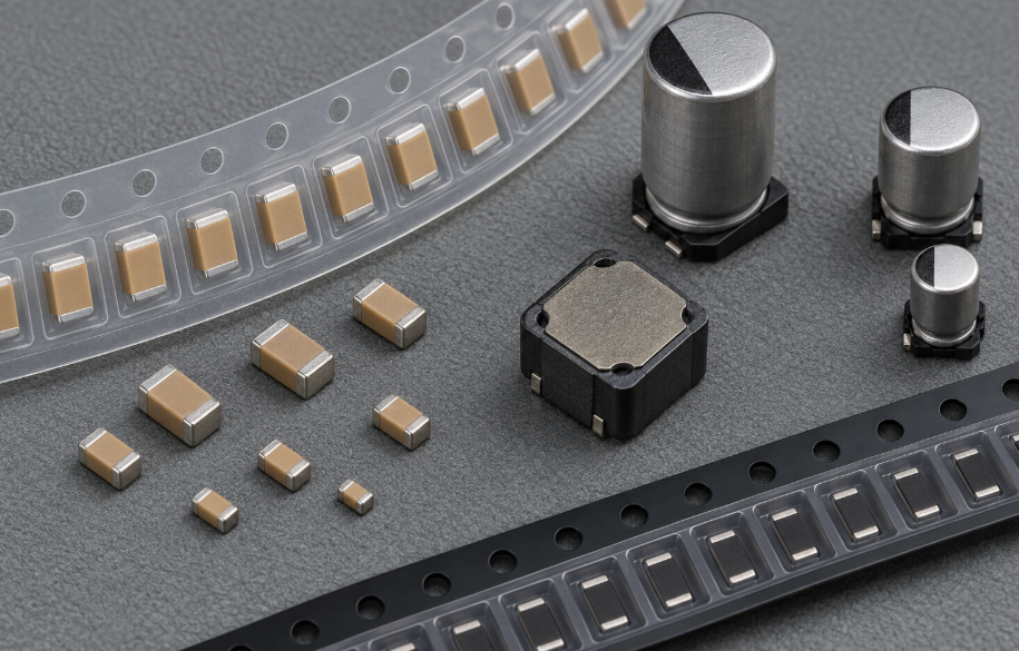
Capacitors store energy in an electric field. They support supply decoupling, bulk energy storage, filtering, timing, and signal coupling. Common PCB types include multilayer ceramic capacitors (MLCCs), aluminum electrolytic capacitors, tantalum capacitors, and film capacitors. See our capacitor guide for a closer look at capacitor types and how operating conditions affect selection.
Ceramic chip capacitors often look alike despite different capacitance, voltage ratings, and dielectric characteristics. Polarized capacitor orientation must follow the package datasheet; polarity markings are not identical across capacitor technologies.
Nominal capacitance alone can be misleading. High dielectric constant MLCCs, including X5R and X7R types, can lose capacitance under applied DC voltage. Murata’s DC bias explanation shows why the operating voltage belongs in an alternate review. Compare the candidate’s capacitance-versus-voltage data rather than assuming two equally labeled parts perform alike.
Specify capacitance, tolerance, dielectric, voltage, package, and temperature range. For electrolytic capacitors, also review equivalent series resistance (ESR), ripple-current rating, and endurance under the stated conditions. DuoLink’s capacitor category can help organize an inquiry, but suitability still depends on the exact manufacturer part number.
Inductors
Inductors store energy in a magnetic field. Power inductors are common in switching converters, while smaller RF inductors support tuning and impedance matching. Chokes are used for filtering, with construction and performance chosen for the noise or current involved. Our guide to inductor types used in electronic circuits compares construction, materials, and application requirements.
A shielded power inductor may look like a square molded block. Other inductors use visible windings or small chip packages. Ferrite beads can resemble chip inductors, but their lossy, frequency-dependent impedance serves a different filtering purpose; they are not automatic substitutes.
Two current specifications deserve attention. Saturation current relates to a defined decrease in inductance as current increases. A thermal current rating relates to a defined temperature rise under the manufacturer’s test conditions. Neither is a universal safe operating current for every PCB environment. Coilcraft’s current and temperature guidance explains the distinction.
Compare inductance, tolerance, DC resistance, peak-current behavior, heating, dimensions, and shielding. Ask engineering to review the candidate at the intended switching frequency and temperature. A matching inductance value does not settle losses or magnetic interference.
Diodes
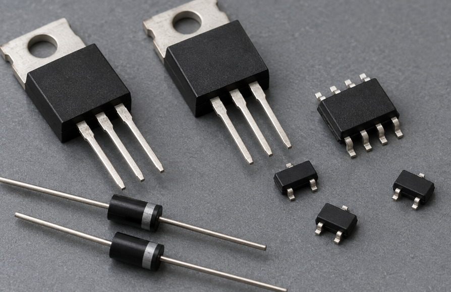
Diodes provide functions such as rectification, signal steering, reverse-polarity protection, voltage referencing, and transient suppression. Their behavior depends on the device type and the way it is connected. The diode types and functions guide explains those roles and the ratings that matter when comparing devices.
Standard rectifiers, Schottky diodes, Zener diodes, and transient-voltage-suppression (TVS) diodes belong to the same broad family, but perform different jobs. A TVS device selected for a data line is not interchangeable with a power rectifier simply because both fit the same pads.
Check forward current, reverse-voltage rating, leakage, surge capability, recovery behavior where relevant, and temperature limits. For TVS devices, compare standoff voltage, breakdown voltage, clamping behavior at the stated test current, and capacitance for signal applications.
Confirm the diode’s function before comparing substitutes. Verify polarity and package pin assignments against the datasheet and assembly drawing. A band or top mark is an identification clue, not enough evidence to approve a shipment.
Transistors
Transistors switch or amplify electrical signals. Bipolar junction transistors (BJTs) are commonly used in small-signal amplification and switching; MOSFETs are widely used in power switching, motor control, and load management. For bipolar devices specifically, see our BJT guide to NPN and PNP transistors; its selection checks should not be applied to MOSFETs as though they were the same device type.
A three-lead package does not establish transistor type or pinout. Similar packages can contain different devices, and two transistors with the same outline may have different terminal assignments.
For a BJT, compare polarity, voltage and current limits, gain under relevant conditions, switching behavior, and thermal performance. For a MOSFET, review channel type, drain-source voltage, on-resistance at the available gate-drive voltage, gate charge, and thermal limits. Gate threshold voltage describes the onset of conduction under specified conditions; it does not establish low-resistance operation at the required load.
Have engineering approve the drive conditions and thermal assumptions before accepting an alternate. A headline current rating may depend on case temperature, PCB copper, or other conditions that the finished product cannot provide.
Integrated Circuits (ICs)
Integrated circuits combine multiple electronic elements within a semiconductor device. PCB assemblies use them for processing, memory, power management, amplification, sensing, logic, and communications. Our integrated circuit guide covers IC types, functions, packages, and application-level selection checks.
Packages range from leaded SOIC and QFP formats to leadless QFN and ball-grid-array (BGA) formats. Pin count and package appearance do not identify functionality. Even closely related IC variants may differ in temperature grade, memory size, voltage range, or supported features.
Preserve the complete manufacturer part number in the BOM and quotation. Suffixes may identify package, grade, packing format, or other options; interpret them using that manufacturer’s ordering information. A short package marking is not always the full orderable part number.
Review the exact variant, lifecycle status, and applicable product-change notices. Define whether firmware compatibility, programming, or hardware revision matters before approving a replacement. For sourcing inquiries, DuoLink’s integrated circuit category covers several IC families, but each quoted line should retain its full identity.
For moisture-sensitive packages, agree the required dry-pack condition and handling information before delivery. Do not assume all ICs share the same moisture sensitivity or baking instructions.
LEDs
Light-emitting diodes convert electrical energy into light. On a PCB, they provide status indication, display functions, backlighting, or illumination. They are a diode category, but optical requirements justify reviewing them separately.
Through-hole indicator LEDs and surface-mount LEDs differ in size and mounting style. Multicolor devices may have several terminals, so package shape alone cannot establish polarity or internal connections.
Match color or wavelength, forward-current requirements, forward-voltage characteristics, viewing angle, and luminous output under the specified conditions. White LEDs may also require a defined color-temperature or chromaticity range. Optical bins are manufacturer-defined groups, and their meaning must be checked in the product documentation.
Include acceptable brightness and color bins when visual consistency matters. A replacement that fits electrically can still create uneven indicators or an inconsistent display. Do not assume a bare LED includes current limiting; verify the circuit or module design.
Crystals and Oscillators
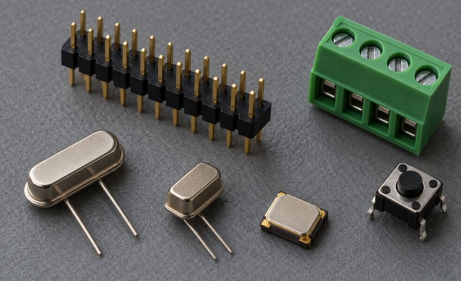
Crystals and oscillators provide timing references for processors, communications devices, and real-time clocks. A quartz crystal is a resonator that works with an oscillator circuit. A packaged oscillator includes the circuitry needed to produce a clock output when powered and enabled as specified.
These devices may use metal cans or compact surface-mount packages. Package appearance is not a reliable way to distinguish a crystal from a complete oscillator, and the same nominal frequency does not establish interchangeability.
For crystals, review frequency tolerance, temperature stability, load capacitance, equivalent series resistance, drive level, and aging requirements. For packaged oscillators, compare supply voltage, output format, enable behavior, jitter where relevant, and pinout. Crystal load capacitance must be evaluated with the actual oscillator circuit and PCB parasitics.
State whether the BOM requires a crystal or an oscillator. Have engineering review startup and timing performance for any alternate, especially when communication accuracy or low-power operation depends on the clock source.
Connectors
Connectors join a PCB to cables, other boards, power sources, or external equipment. Common forms include pin headers, sockets, terminal blocks, board-to-board connectors, and USB receptacles.
Mechanical fit is only part of the requirement. Two connectors may share pin count and pitch but differ in keying, locking, contact arrangement, mounting height, or the mating interface. A drawing is often more useful than a product photograph.
Compare contact ratings under the relevant conditions, contact material and plating, retention, mating cycles, orientation, and assembly method. For high-speed signals, review the electrical requirements of the complete connection. A familiar interface shape does not guarantee support for every protocol or power feature associated with that interface.
Confirm the exact mating part and approved PCB footprint. Request dimensional drawings and evaluate samples for critical mechanical substitutions. A connector should not reach production simply because its pins enter the holes.
Switches
Switches make, break, or select electrical connections. Tactile pushbuttons, slide switches, DIP switches, and rotary switches appear on boards for user input, mode selection, reset, and configuration.
Selection depends on contact arrangement and application. A momentary switch returns when released; a maintained switch stays in its selected position. Pole and throw terminology describes how many circuits and connection paths the switch controls.
Check rated load, contact resistance, operating force, actuator height, travel, durability, and soldering conditions. Mechanical life and electrical life describe different test conditions, so a large cycle count needs context.
Match the switch to the enclosure as well as the PCB. For low-level logic inputs, verify suitability for small signal loads. Contact bounce may require hardware or firmware handling; the switch purchase cannot resolve that design requirement by itself.
Relays
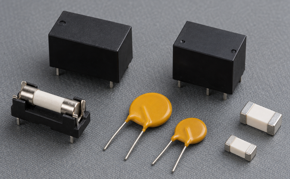
Relays allow an electrical control signal to switch another circuit. Electromechanical relays use a coil to move contacts and are common in industrial controls, appliances, and power switching. Solid-state relays perform switching electronically and have different operating characteristics. See our relay types and applications guide to compare switching structures, load requirements, and operating behavior.
For electromechanical devices, match coil voltage, coil power, contact arrangement, contact ratings, and footprint. Normally open and normally closed contacts must match the intended operating state. A latching relay also needs the correct control method.
The load type matters. Resistive, inductive, and capacitive loads impose different switching stresses, and an AC contact rating cannot simply be applied to a DC load. Inrush and electrical endurance deserve review under the actual application conditions.
Ask for the rating applicable to the real load, rather than relying on the largest current printed in a catalog. Have engineering review coil suppression, release timing, and isolation requirements for the exact model. Do not approve a safety-critical relay substitute from size and coil voltage alone.
Fuses and Resettable Fuses
Fuses protect circuits against specified overcurrent conditions. A conventional fuse opens when its element melts and normally requires replacement. Polymer positive-temperature-coefficient (PPTC) devices, often called resettable fuses, transition to high resistance when sufficiently heated by a fault.
A PPTC limits current rather than providing the same open circuit as a conventional fuse. Current still flows in its tripped state, and recovery depends on the device cooling after fault energy is removed or sufficiently reduced. Littelfuse’s PPTC guidance explains why protection type and temperature conditions matter.
For conventional fuses, compare current and voltage ratings, AC or DC suitability, breaking capacity, time-current behavior, and pulse withstand. For PPTCs, compare hold current, trip current, maximum voltage, fault-current limits, resistance, and temperature derating.
Do not interchange conventional fuses and PPTCs without a protection review. Match the fault response to the circuit and applicable product requirements. A current rating alone does not determine how quickly the device responds or whether it will provide the required protection.
How to Source Common Electronic Components for a PCB
A useful RFQ starts with the approved BOM. Include manufacturer, complete part number, quantity, required delivery date, and acceptable packaging. Separate approved alternates from parts that still need engineering review.
Use a short evidence checklist before committing to an order:
| Check | Evidence to request | When to pause approval |
|---|---|---|
| Part identity | Full manufacturer part number, ordering information, datasheet | A suffix, grade, pinout, or footprint differs |
| Supply condition | Stock location, quantity confirmation, packaging and lot photos | Listed availability has not been confirmed |
| Traceability | Available origin and chain-of-custody records; agreed lot details | Evidence does not meet the project’s requirements |
| Handling | Relevant ESD, moisture, and packaging information | Moisture history or handling condition is uncertain |
| Material requirements | Current part-specific manufacturer declarations where required | Documents do not cover the ordered variant |
| Substitution | Documented comparison and engineering approval | Compatibility is based only on appearance or nominal value |
For overseas purchases, agree documentation needs before shipment. EU customers may request RoHS and REACH information, while automotive, medical, or aerospace projects may impose additional customer and application requirements. Component documentation does not by itself establish compliance of the finished product.
At receiving, compare shipment labels and documents with the purchase order, then inspect packaging and representative parts under an agreed plan. Quarantine unexplained mismatches until they are resolved. Visual inspection helps screen condition and identity; it does not, by itself, prove authenticity or full electrical performance.
Conclusion
Knowing the common electronic components on a PCB helps purchasing and engineering teams ask better questions. The dependable buying decision comes from matching the complete part specification, checking the supply evidence, and approving changes before production.
DuoLink Electronics is an independent electronic-component supplier supporting IC, semiconductor, passive-component, connector, and hard-to-find part sourcing. To submit a BOM or component inquiry, provide manufacturer part numbers, quantities, delivery needs, target application, and any date-code, packaging, or documentation requirements. These details help the team review supply options and identify questions that need confirmation before an order.
Frequently Asked Questions
What are the most common electronic components on a PCB?
Common electronic components include resistors, capacitors, inductors, diodes, transistors, ICs, LEDs, timing devices, connectors, switches, relays, and overcurrent-protection devices. The mix depends on the board’s function; many boards do not use relays or separate crystals.
Can I identify a component from its PCB label?
Reference designators such as R, C, L, D, Q, and U often indicate component categories, but conventions vary. Use the schematic, BOM, assembly drawing, and datasheet to confirm the exact part. A designator does not specify its rating or orderable number.
Are surface-mount and through-hole components interchangeable?
They can serve similar circuit functions, but usually require different footprints and assembly methods. Substitution may also change electrical, thermal, or mechanical behavior. Engineering must approve the change, and the PCB may need redesign.
Can I use a part with a higher voltage or current rating?
A higher rating alone does not establish compatibility. Other parameters, including capacitance under bias, gate drive, leakage, switching behavior, dimensions, and protection response, may differ. Compare the relevant datasheets and application conditions.
Do component photos or date codes prove authenticity?
No. Photos and date codes support identity and condition checks, but do not establish authenticity or storage history on their own. Review sourcing records and agree any additional inspection or testing appropriate to the application risk.


 English
 German
 Spanish
 French
 Chinese
 Italian