If you work in electronics procurement, hardware design, or supply chain management, you have almost certainly faced a BOM line that reads “analog IC” or “digital IC” without much else to go on. The two categories share the same physical packaging — plastic, ceramic, leads, pads — yet they process electrical signals in fundamentally different ways. Choosing the wrong type, or sourcing a substitute that crosses the boundary, can break a design completely.
This article breaks down what analog and digital ICs actually are, how each one processes signals, where each category is used in real applications, and — critically — how to make the right choice when your project requires you to decide between them. Whether you are evaluating supplier datasheets, auditing a vendor BOM, or designing from scratch, understanding this distinction will save you time and prevent costly mistakes.
What Is an Integrated Circuit?
Basic Structure and Function of an IC
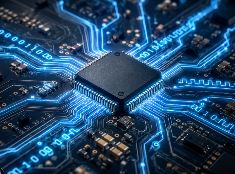
An integrated circuit is a miniaturized electronic assembly built onto a single piece of semiconductor material — almost always silicon. Dozens, thousands, or billions of transistors, resistors, capacitors, and diodes are fabricated directly onto that silicon die, then connected by metal traces just micrometers wide. The die is then encapsulated in a protective package — DIP, SOIC, QFP, BGA — with external pins or pads that connect it to a printed circuit board.
The genius of the IC is density. A single chip the size of your thumbnail can contain functionality that would have required an entire room of discrete components fifty years ago. That miniaturization is what makes modern smartphones, industrial PLCs, and medical monitoring devices physically possible. From a procurement standpoint, sourcing one IC is simpler, more reliable, and more cost-effective than sourcing and assembling dozens of discrete parts.
How ICs Process Electrical Signals
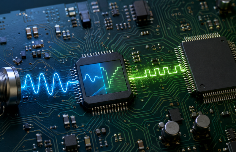
Every IC ultimately works with electrical signals — voltages and currents that carry information. The way an IC manipulates those signals determines its category. Some ICs amplify, filter, or regulate signals while preserving the continuously variable nature of the original electrical waveform. Others convert signals into a series of binary states — on or off, one or zero — and perform computations on those discrete values.
The processing method matters enormously in practice. A signal from a temperature sensor is a slowly varying voltage that represents real-world heat. A processor running firmware cares only about whether a voltage is above or below a threshold. Both start with electricity, but what they do with it is entirely different — and that difference defines analog versus digital.
Why ICs Are Classified as Analog or Digital
The classification exists because signal type determines circuit architecture. Analog ICs are built around transistors operating in their linear region — continuously varying output in proportion to a continuously varying input. Digital ICs use transistors as switches, fully on or fully off, processing signals through logic gates. The two architectures demand different design philosophies, different fabrication processes, different testing protocols, and different sourcing considerations.
There is also a third category worth noting early: mixed-signal ICs. These combine both analog and digital circuitry on a single die — analog-to-digital converters (ADCs), digital-to-analog converters (DACs), and power management ICs with digital control interfaces are common examples. We will return to mixed-signal devices later, as they are increasingly important in modern system design.
What Is an Analog IC and How Does It Work?
Understanding Continuous Analog Signals
An analog signal can take any value within a continuous range. A microphone output might vary between 0 mV and 100 mV as you speak — every tiny fraction of a millivolt is meaningful. A pressure sensor measuring hydraulic flow produces a voltage that rises and falls proportionally with physical pressure. These signals carry information in their exact amplitude, not just in whether they are high or low.
The challenge with analog signals is that they are vulnerable to corruption. Any noise introduced into the signal path — from power supply ripple, electromagnetic interference, thermal noise in resistors, or ground bounce — gets amplified along with the signal itself. Managing that noise is the central challenge of analog circuit design, and it is why analog ICs require careful PCB layout, proper decoupling, and shielded routing in sensitive applications.
How Analog ICs Amplify, Filter, and Regulate Signals
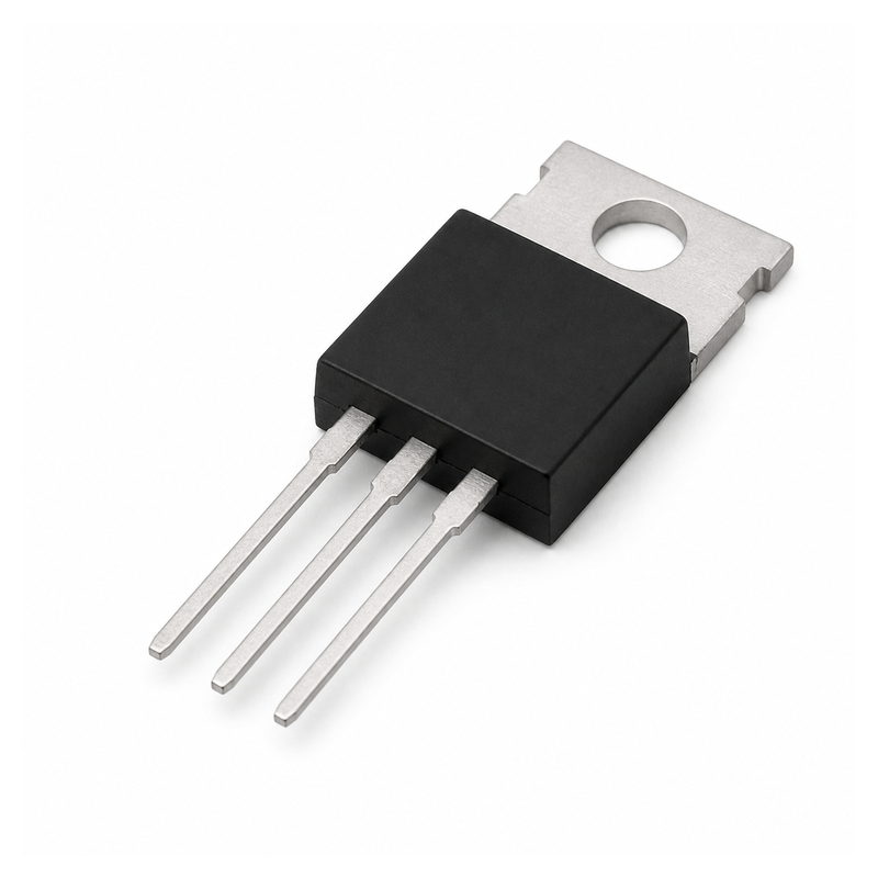
Analog ICs perform three primary functions: amplification, filtering, and regulation. An operational amplifier (op-amp) takes a weak input signal and multiplies it by a gain factor set by external resistors. A low-pass filter IC attenuates frequencies above a cutoff point, removing high-frequency noise from a sensor output. A linear voltage regulator takes an unsteady input voltage and produces a stable, precise output — the LM7805, for example, outputs a fixed 5 V regardless of whether the input is 7 V or 12 V.
What all of these functions have in common is that the output is always a continuously varying analog of the input. The amplifier does not care whether the input is 10 mV or 10.3 mV — it amplifies both proportionally. That proportionality is both the strength and the limitation of analog processing: it is real-time and precise, but it is also sensitive to component tolerances, temperature drift, and noise.
Common Types of Analog ICs
Operational Amplifiers (Op-Amps): The fundamental building block of analog signal conditioning. Used for amplification, buffering, comparison, and active filtering. Manufacturers such as Texas Instruments, Analog Devices, and STMicroelectronics produce op-amps in almost every package and performance tier imaginable.
Voltage Regulators (LDOs and DC-DC): Linear regulators (LDOs) provide clean, low-noise output at the cost of efficiency. Switching regulators (DC-DC converters) sacrifice some noise performance for higher efficiency. Both are essential in power management design.
Instrumentation Amplifiers: A specialized differential amplifier with extremely high common-mode rejection ratio (CMRR). Widely used in medical devices, load cells, and precision measurement equipment where small signals must be amplified in the presence of large common-mode interference.
Comparators: Compare two voltages and output a high or low signal indicating which is larger. Often used at the boundary between analog and digital domains — for example, triggering a digital interrupt when a sensor voltage crosses a threshold.
Current Sense Amplifiers: Measure current flow by amplifying the small voltage drop across a sense resistor. Critical in battery management, motor control, and power monitoring applications.
What Is a Digital IC and How Does It Work?
Understanding Binary Signals and Logic Levels
A digital IC operates on binary logic: a voltage above a defined threshold is interpreted as logic “1” (HIGH), and a voltage below another threshold is logic “0” (LOW). In a 3.3 V CMOS system, for example, anything above roughly 2.0 V is HIGH and anything below 0.8 V is LOW. The voltage range in between is the forbidden zone — valid signals should spend as little time there as possible.
This binary abstraction is what makes digital systems robust against noise. A noise spike of 200 mV on a logic HIGH signal (say, 3.1 V in a 3.3 V system) does not change the outcome — the IC still reads it as “1”. That noise immunity is the most significant practical advantage of digital over analog processing, especially in electrically noisy industrial and automotive environments.
How Digital ICs Process and Store Data
Digital ICs process data through logic gates — AND, OR, NOT, NAND, NOR, XOR — which are the fundamental building blocks of all digital computation. Combining gates produces flip-flops (which store a single bit), registers (which store multiple bits), and arithmetic logic units (which add, subtract, compare, and shift numbers). Millions of these structures, working together under the control of a clock signal, are what enable a microprocessor to execute billions of instructions per second.
Memory functions in digital ICs follow a similar principle. SRAM cells use cross-coupled inverters to hold a bit as long as power is applied. Flash memory uses floating-gate transistors that trap charge even without power. In either case, the “0” or “1” is a physical state — not an analog level — which is why digital memory is far more reliable and scalable than analog storage.
Common Types of Digital ICs
Microcontrollers (MCUs): A complete computer on a single chip — CPU core, flash memory, RAM, timers, and peripherals. The STM32, PIC, and ESP32 families are well-known examples. MCUs are the backbone of embedded systems in appliances, industrial sensors, and IoT nodes.
Microprocessors (MPUs): High-performance CPU cores without integrated memory. Used in smartphones, servers, and computing applications where operating systems run on external RAM and storage. Intel Core and AMD Ryzen are the dominant consumer examples; ARM Cortex-A series dominates embedded Linux applications.
FPGAs (Field-Programmable Gate Arrays): Reconfigurable logic arrays that can implement virtually any digital circuit in hardware. Used in prototyping, signal processing, and applications where custom hardware acceleration is needed without the cost of ASIC development.
Logic Gates and Standard Logic ICs: 74-series devices (74HC00, 74LS245, etc.) implement individual logic functions — buffers, inverters, multiplexers. Simple but indispensable for signal routing, level shifting, and glue logic between larger ICs.
Memory ICs: SRAM, DRAM, NAND Flash, and NOR Flash cover a wide range of speed, capacity, and retention requirements. Choice depends on read/write cycle requirements, power constraints, and whether non-volatility is needed.
ASICs (Application-Specific Integrated Circuits): Custom-designed digital chips optimized for one specific function — cryptocurrency mining hardware, video codec chips, and network switch silicon are typical examples. High up-front cost, lowest per-unit cost at volume.
Analog IC vs Digital IC: Key Differences
Signal Type and Processing Method
The most fundamental difference is how each IC handles its input signal. Analog ICs maintain a continuous relationship between input and output — the output is always a scaled, filtered, or transformed version of the input voltage or current. Digital ICs, in contrast, first quantize the input into discrete binary values and then operate on those values using logic. The moment you quantize, you lose infinitely fine resolution — but you gain immunity to noise, repeatability, and the ability to perform arbitrarily complex computations.
This distinction has direct procurement consequences. Analog ICs are often characterized by continuous performance parameters: bandwidth, gain-bandwidth product, CMRR, offset voltage, noise density. Digital ICs are characterized by discrete performance metrics: operating frequency, logic family (CMOS, TTL, ECL), interface protocol, and memory capacity. Understanding which parameters matter for your application determines which datasheet sections to prioritize when evaluating alternatives.
Accuracy, Noise Sensitivity, and Power Consumption
Analog ICs deliver real-time, continuous output but are inherently sensitive to noise, temperature, and component variation. A precision op-amp with a 1 µV/°C offset drift will introduce measurable error in a high-precision application if temperature changes significantly. Digital ICs are repeatable and predictable — the same code produces the same output regardless of temperature, as long as the chip operates within its specified range.
Power consumption follows different patterns. A linear voltage regulator dissipates power proportional to the voltage drop across it — heat is the price of analog simplicity. A digital IC’s power consumption scales with switching frequency and supply voltage; at rest it can be extremely low, but active computation draws significant current. This difference shapes system power budget decisions, especially in battery-powered designs where both idle and active current matter.
Circuit Complexity and Integration Level
Analog ICs are generally simpler in transistor count but harder to design. Getting an op-amp circuit to meet noise and bandwidth specifications across temperature and process variation requires deep analog expertise. Digital ICs contain vastly more transistors — a modern CPU has billions — but their design complexity is managed by abstraction layers: logic synthesis, place-and-route tools, and firmware.
From a sourcing perspective, analog ICs tend to have longer product lifecycles but narrower interoperability. A specific instrumentation amplifier from one manufacturer may not be drop-in replaceable with a similar device from another without re-characterizing the gain network. Digital ICs, especially those following established standards (DDR5 DRAM, USB controllers, CAN transceivers), have more predictable interoperability, though register-level compatibility still requires verification.
Key Differences at a Glance:
| Parameter | Analog IC | Digital IC |
|---|---|---|
| Signal Type | Continuous (infinite values) | Discrete (0 or 1 only) |
| Processing Method | Direct amplification / filtering | Binary logic operations |
| Noise Sensitivity | High — noise corrupts signal | Low — noise margin absorbs interference |
| Power Consumption | Moderate; varies with load | Lower at rest; spikes during switching |
| Design Complexity | Fewer transistors; tricky to tune | Millions of transistors; defined by code |
| Speed | Real-time, no conversion delay | Very fast; limited by clock frequency |
| Precision | Inherently continuous; limited by noise | Defined by bit depth (8-bit, 16-bit, etc.) |
| Integration Level | Low to medium (op-amps, LDOs) | Very high (CPUs, FPGAs, SoCs) |
Where Are Analog ICs Used?
Power Management and Voltage Regulation
Power management is arguably the most ubiquitous analog IC application. Every electronic system that runs from a battery, USB port, or AC adapter requires voltage conversion and regulation. LDO regulators handle the final stage of power conditioning, providing clean, stable supply rails to sensitive analog circuitry — audio front-ends, RF receivers, and precision sensors all depend on low-noise LDOs to maintain signal integrity.
Switching regulators (buck, boost, buck-boost topologies) appear wherever efficiency matters more than noise. A buck converter running at 95% efficiency dissipates far less heat than a linear regulator dropping 5 V to 3.3 V at 500 mA — the math is straightforward, but the PCB layout implications are not. Proper placement of inductors, capacitors, and the switching node are all analog engineering problems, even when the controller IC has a digital interface.
Audio, Sensor, and Communication Circuits
Audio circuits are almost entirely analog from the microphone input to the speaker output, with digital processing in between. Microphone amplifiers condition weak microphone signals before an ADC digitizes them. Speaker drivers amplify DAC outputs back to line or speaker levels. Even in fully digital audio systems, the first and last stages are invariably analog — the physical world does not speak binary.
Sensor interfaces rely heavily on analog ICs. Pressure, temperature, humidity, strain, and current sensors all produce analog outputs that need conditioning before a microcontroller can read them. Instrumentation amplifiers reject common-mode interference on long cable runs. Anti-aliasing filters remove high-frequency content before ADC sampling. Signal conditioning is a practical engineering discipline, not a theoretical one — get it wrong and your sensor data is noisy, drifted, or outright wrong.
In RF and wireless communication, analog ICs handle the physical-layer tasks: low-noise amplifiers (LNAs) amplify received signals without adding noise, mixers translate frequencies between RF and baseband, and power amplifiers drive antennas. Even 5G base stations, which use massive digital signal processing, depend on analog front-end ICs to interface with the physical radio spectrum.
Automotive, Medical, and Industrial Equipment
Automotive electronics present some of the most demanding analog IC requirements anywhere: wide temperature range (−40 °C to 150 °C), vibration resistance, EMC compliance, and functional safety certifications (AEC-Q100 qualification). Gate driver ICs control IGBT and MOSFET switches in inverters for electric vehicle drivetrains. Battery management ICs monitor cell voltage and temperature with millivolt accuracy across 400 V battery packs. Sensor ICs for wheel speed, throttle position, and airbag triggering must operate reliably in environments that would destroy ordinary consumer-grade devices.
Medical applications demand similar rigor. Biopotential amplifiers for ECG, EEG, and EMG measurements work with signals in the microvolt-to-millivolt range, in the presence of strong common-mode interference from the power grid. Isolation amplifiers protect both patients and equipment from dangerous ground loops. Every analog IC in a medical device typically requires extensive characterization, qualification, and traceability — factors that directly affect procurement strategy and acceptable sources.
Industrial equipment relies on analog ICs for 4–20 mA current loop interfaces, which transmit sensor data over long cable runs in electrically noisy factory environments. Isolation amplifiers, current sense ICs, and precision references are standard components in PLCs, motor drives, and process instrumentation.
Analog IC Applications by Industry:
| Industry | Typical Analog IC Functions | Example Devices |
|---|---|---|
| Power Management | Voltage regulation, DC-DC conversion | LDO regulators, PWM controllers |
| Audio & Consumer | Signal amplification, filtering | Op-amps, Class-D amplifiers |
| Automotive | Sensor conditioning, motor drive | Hall-effect sensor ICs, gate drivers |
| Medical | Biopotential amplification, ADC front-end | Instrumentation amplifiers, ADCs |
| Industrial | 4–20 mA signal conditioning | Isolation amplifiers, current sense ICs |
Where Are Digital ICs Used?
Computers, Servers, and Consumer Electronics
General-purpose computing is the domain where digital ICs reach their highest complexity. A modern server CPU contains tens of billions of transistors, executing instructions out-of-order, managing multi-level cache hierarchies, and handling dozens of simultaneous threads — all in a chip that fits in a palm-sized package. The surrounding ecosystem — DDR5 memory controllers, PCIe switches, NVMe storage controllers — is equally dense with digital logic.
Consumer electronics leverage digital ICs for media processing, display driving, and wireless connectivity. A smartphone SoC (system-on-chip) integrates CPU cores, GPU, image signal processor, modem, and security elements into a single package. The image signal processor alone contains dedicated digital hardware for noise reduction, HDR processing, and computational photography — functions that would require rooms of discrete analog circuitry just a generation ago.
Embedded Systems and Industrial Controllers
Embedded systems are where digital ICs truly earn their keep in industrial and commercial applications. A microcontroller running at 64 MHz, monitoring eight analog inputs through its built-in ADC, controlling three PWM outputs, and communicating over CAN and SPI — all simultaneously, drawing 10 mA — represents a level of functionality that would have required multiple expensive discrete devices twenty years ago.
Industrial controllers depend on digital ICs for deterministic timing. A PLC executing a ladder logic program needs guaranteed cycle times — a missed scan could mean a conveyor belt does not stop in time, or a valve does not open at the right moment. Real-time operating systems (RTOS) running on ARM Cortex-M cores provide the determinism that safety-critical industrial applications require. FPGAs add another layer: when even an RTOS is too slow, direct hardware implementation of logic functions in an FPGA delivers nanosecond-level timing precision.
Communication, Automotive, and IoT Devices
Network infrastructure is built almost entirely on digital ICs. Ethernet switch ASICs route traffic between hundreds of ports at terabit-per-second aggregate speeds. Network processor ICs run deep packet inspection in hardware. Optical transport systems use digital signal processing ICs to compensate for chromatic dispersion across thousands of kilometers of fiber — a function that purely analog approaches cannot accomplish with the required precision.
Modern automotive electronics are increasingly digital at the system level. An electric vehicle’s drivetrain controller might run a 200 MHz ARM Cortex-R core for real-time motor control, communicate over CAN FD and Ethernet, and run AUTOSAR-compliant software. Body control modules handle dozens of inputs and outputs — door locks, window motors, exterior lighting — through microcontrollers that execute millions of instructions per second while idling at low power between events.
IoT devices represent perhaps the broadest application of digital ICs in terms of deployment volume. Billions of nodes — smart meters, connected sensors, asset trackers — use ultra-low-power microcontrollers and wireless SoCs. Devices like the Nordic nRF52 or Silicon Labs EFR32 integrate Bluetooth LE, Zigbee, or Thread radio with a 32-bit CPU core and run for years on a coin cell battery. The system design challenge is almost entirely digital: firmware, protocol stack, and power state management.
Digital IC Applications by Industry:
| Industry | Typical Digital IC Functions | Example Devices |
|---|---|---|
| Computing & Servers | Processing, memory management | CPUs, DDR controllers, FPGAs |
| Consumer Electronics | Video decoding, UI processing | SoCs, display driver ICs |
| Industrial Control | PLC logic, motion control | Microcontrollers, DSPs |
| Communication | Protocol handling, signal encoding | Network ASICs, RF transceiver ICs |
| Automotive & IoT | ECU processing, wireless connectivity | ARM-core MCUs, BLE SoCs |
How to Choose Between Analog and Digital ICs
Determine the Signal and System Requirements
Start with the signal itself. If your system processes real-world physical quantities — temperature, pressure, sound, light, current — you will need analog ICs at the interface. The question is how much of the processing chain remains analog before digitization. A simple thermostat might convert temperature to a digital value with a one-chip solution (a temperature sensor IC with I2C output). A precision calorimeter might require a dedicated instrumentation amplifier, precision ADC, and voltage reference before any digital processing begins.
Think about resolution and dynamic range. If you need to measure a signal that varies by a factor of a million — say, audio ranging from near silence to near clipping — you need analog circuits with sufficient dynamic range before digitization. A 16-bit ADC provides 96 dB of dynamic range in theory, but the analog front-end must be quiet enough not to fill that range with noise. The analog domain sets the ceiling; the digital domain cannot recover information that was lost to noise at the input stage.
Compare Speed, Accuracy, Power, and Cost
Speed requirements often determine the answer. High-speed RF signal processing at gigahertz frequencies may require analog ICs because no digital system can process at that rate directly — the ADC itself becomes the bottleneck, and bandwidth-limited analog pre-processing is unavoidable. Conversely, if your application is relatively slow (sub-kilohertz data rates) and requires complex decision-making — threshold detection, averaging, protocol decoding — a digital microcontroller will handle it more flexibly and probably more cheaply than a custom analog circuit.
Accuracy and long-term stability matter differently for each type. A precision analog voltage reference might drift 5 ppm/°C — acceptable in a controlled environment, problematic in a vehicle or outdoor enclosure. A digital computation is perfectly accurate within its bit resolution and does not drift. For applications requiring calibration, analog circuits may need factory-calibrated trim or on-the-fly software compensation, adding both cost and complexity.
Power and cost are system-level decisions, not component-level ones. An LDO regulator is cheap and simple but wastes power as heat. A switching regulator is more efficient but adds BOM complexity — inductor, output capacitor, control IC. In high-volume consumer products, that efficiency difference translates directly into battery size, product dimensions, and material cost. Work through the system power budget before locking in the IC topology.
Consider Mixed-Signal ICs for Combined Functions
Mixed-signal ICs increasingly blur the boundary between analog and digital. A power management IC (PMIC) might contain multiple switching regulators, LDOs, an ADC for battery monitoring, and an I2C interface for software control — all on one die. A microcontroller with built-in ADCs and DACs handles sensor reading and signal output without external conversion ICs. An audio codec IC performs the entire analog input/output function with digital control, reducing BOM count significantly.
When evaluating mixed-signal ICs, scrutinize the analog performance specifications as carefully as the digital ones. A built-in ADC with mediocre noise performance can undermine a design that would otherwise benefit from the cost and area savings of integration. Read the datasheet carefully — particularly the electrical characteristics tables under the analog sections — and verify that the integrated analog performance meets your application requirements before committing to a single-chip solution.
For sourcing decisions, mixed-signal ICs introduce unique challenges: they are often proprietary, harder to second-source, and may carry longer lead times than commodity digital logic or standard analog components. Build that risk into your procurement planning, especially for production designs where supply continuity matters.
Conclusion
The distinction between analog and digital ICs is not just a textbook category — it is a practical engineering and procurement consideration that affects every stage of a product’s lifecycle, from schematic design through sourcing, qualification, and production. Analog ICs handle the physical world’s continuous signals with real-time fidelity but require careful noise management and component selection. Digital ICs bring computation power, noise immunity, and scalability, but they cannot operate in isolation — they always need an analog interface to the real world.
Understanding where each type belongs, and recognizing where mixed-signal devices can simplify your BOM, positions you to make better technical decisions and avoid the kind of sourcing mistakes that come from treating ICs as interchangeable black boxes. Whether you are evaluating a replacement for an obsolete op-amp or designing the power management architecture for a new IoT platform, the fundamentals covered here apply directly.
If you are sourcing integrated circuits — whether analog, digital, or mixed-signal — Duolink Electronics is an independent electronic component distributor carrying ICs, semiconductors, passive components, connectors, and more. We support BOM procurement, part number lookups, inventory verification, and hard-to-find component sourcing. Reach out through our website or contact our team directly on WhatsApp — we are ready to help you find what your project needs.


